The efficiency of half wave rectifier is 40.6%. That means only 40.6% of the input AC current gets converted to DC. 50% power in the negative half cycle is not converted and the remaining 9.4% is lost in the circuit.
This is the third chapter in the Rectifier series. So we suggest to go through some of the related topics.
Recommended Reads Before Going Forward:
Though we have covered various properties in our last article but kept aside a mathematical derivation of the half-wave rectifier efficiency equation. Because it is better to be explained separately.
In this article, we are going to learn to calculate the equation of efficiency of the half-wave rectifier and about its various applications in detail.
Before learning ahead, let’s have a little recap about the working of a half-wave rectifier.
In Half wave rectifier, the diode conducts only for positive input voltages i.e. one-half of the AC wave is removed because it cannot pass through the diode. As the name indicates it rectify only half of the input wave through the phenomenon name as rectification.
Now let’s go ahead and get to the mathematical part.
What is Rectifier Efficiency
The ratio of DC power obtained at the output to the applied input AC power is known as rectifier efficiency.
Mathematically it can be given as:
η = DC Power Output / AC power input
Where η is Rectifier Efficiency.
Half-wave Rectifier Efficiency Mathematical Calculation
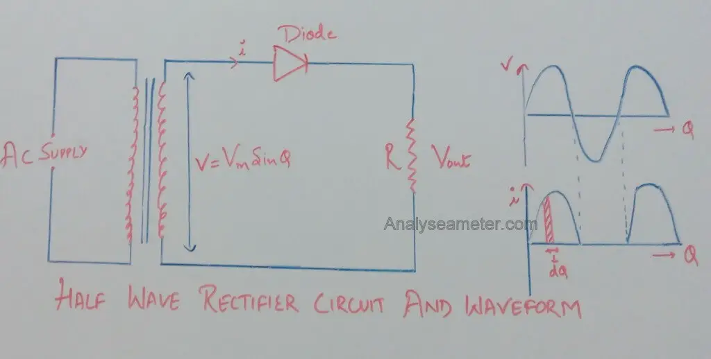
For the determination of the efficiency of the half-wave rectifier consider the circuit diagram shown in the Figure below.
Let rf and RL be the forward resistance & load resistance of the diode. v = Vm sin θ be the voltage appearing across the secondary of the power transformer.
During the positive half cycle, the diode is forward biased making the current flow through the load resistor. While during the Negative half cycle the diode is reverse biased so it stops the current flow through the load resistor.
The waveform diagram at the right side of the above figure shows only a positive waveform at the output and a suppressed negative waveform. During the conduction period its instantaneous value is given by the equation:
i = v / (rf + RL)
v = i (rf + RL)
As we know,
v = Vm sin θ
Therefore,
i = Vm sin θ / (rf + RL)
When sin θ = 1, current = maximum. Therefore,
Im = Vm / (rf + RL)
Where,
i = Im sin θ
Since the output is obtained across RL, therefore
D.C power output = Idc2 RL
= *Iav2 RL
Where,
Iav = ʃ (i dθ) / 2π —-(i)
Integrate equation (i) from 0 to π,
Iav = (1 / 2π) * ʃ Im sin θ dθ
= (Im / 2π) * ʃ sin θ dθ
= (Im / 2π) [ – cos θ ]
= (Im / 2π) [ -(-1-1)]
= 2 (Im / 2π)
= (Im / π)
Therefore, DC power output is given as,
Pdc = Idc2 RL = (Im / π)2 RL
And AC power input is given as,
Pac =Irms2 (rf + RL)
Where,
** Irms = ʃ (i2 dθ) / 2π —- (ii)
Integrate equation (ii) from 0 to π,
= √ (1 / 2π) * ʃ Im2 sin2 θ dθ
= √ (Im2 / 2π) * ʃ ( 1- cos 2θ)/ 2 dθ
= √ (Im2 / 4π) * [ ʃ dθ – ʃ cos 2θ dθ ]
= √ (Im2 / 4π) * [[θ] – [sin 2θ / 2]]
= √ (Im2 / 4π) * [π – 0]
= Im / 2
Therefore, AC power input is given as,
Pac =Irms2 (rf + RL)
=( Im / 2)2 (rf + RL)
And
Rectifier Efficiency (η) = Pdc / Pac
Put the values of Pdc and Pac from above equations, therefore,
η =[ (Im / π)2 * RL ] / ( Im / 2)2 * (rf + RL)
= 0.406 RL / (rf + RL)
= 0.406 / (1+ rf RL)
If rf is neglected as compare to RL then the efficiency of the rectifier is maximum. Therefore,
η max =0.406 = 40.6%
That Means,
The half wave rectifier can convert maximum of 40.6% of AC power into DC power, and the remaining power of 59.4% is lost in the rectifier circuit. Hence the half wave rectifier efficiency is 40.6%. In fact, 50% power in the negative half cycle is not converted and the remaining 9.4% is lost in the circuit.
You can watch this video by Neso Academy for more info.
Half wave rectifier Applications
Half wave rectifier is not so good as compared to Full-wave or Bridge rectifier, but sometimes we require this rectifier depending on the requirements. Some of the applications of half-wave rectifier are
- It is used for the detection of amplitude modulated radio signals.
- For the welding purpose, it supplies polarized voltage.
- It is used in many signal demodulation processes.
Before you Go….
Half Wave Rectifiers are not commonly used as more than half of the input power gets wasted in the process. There is another type of Rectifier that is used most of the time in circuits. If you want to increase your knowledge, you can go to the below link.


Hi. I am a bit confused. The power output is equal to the power input minus losses. For convinience(and in practical terms) let us assume the diode and transformer losses are negligible. So where is the 60 percent power consumed? Thanks
I don’t understand about bipolar Junction transistors BJT
some can explain to me kindly
Hi Vincent,
Here is a small description of the BJT Transistor.
BJT is a 3 terminal device formed by sandwiching a P or N-type semiconductor between 2 N or P-type semiconductor. This form 2 P-N Junctions in series sharing a common P or N-terminal.
For more, you can study from our article here:
Bipolar Junction Transistor
I hope you will understand the concept. If you have any further problem, you can ask in comment.
Thanks dude for this information
Explain why half wave rectifier is called a poor device for rectification??
Hello Rajibul,
The answer to your question is already in the article.
Maximum rectification that can occur in Half wave rectifier is 40.6%. That means, 59.4% of the signal gets waste in the process. Refer to the equation in the article. Below that, there is an explanation. While the efficiency of Full wave rectifier is 81.2%. That means, only 18.8% of the signal get waste.
Hence have wave rectifier is called a poor device for rectification.
If you have any other question, you can ask in the comment.
Sir,
In the input ac power expression why we take RMS value of I. Input current is a full sine wave, but in Irms expression we take only 0 to pi value(half wave o/p).
Please guide me, sir.
Hi Ritesh,
Sorry for late reply… here is the solution.
Irms expression is related from the AC power Type. For full-wave, it is Irms = Ipk/sqrt(2) but for half wave, it is Irms = Ipk/2
Thank You for this
Welcome Saptarshi,
We are glad that you find our website helpful. Share the article with your friends too. This keeps us encourage to produce quality and helpful content. ?
Efficiency is DC power to the load / ac power obtained by the secondary transformer …but the ac power obtained is not DC…it is full wave …then y is the rms value of rectified wave taken into consideration??
See for the negative half cycle there is voltage and current in the primary of the transformer but there is no current in the secondary due to high resistance of reverse biasing. So the waveform of the current is having only positive cycle before entering the diode and coming out of the diode, but no negative cycle. So coming out of it, there is pulsating dc whose output power we calculate. Now before entering the diode the waveform is same, thus if there would be an ac that had the rms value of that current waveform, then what power had it produced is calculated. And thus we solve for the efficiency that what would have been the dc’s effect to that of the ac’s.
Thanks, Shivam for the comment. I don’t know how I skipped this question from Preeti. We are glad that people like you are here to help others.