Today we are going to learn about another important passive electronic component. In our previous article, we have learned about the resistor, now we will talk in detail about a capacitor.
Electronic components are of 2 types, active components, and passive components. Transistors, tunnel diodes are active components while resistors, capacitors etc are passive components.
What is a Capacitor
A Capacitor can be defined as
A capacitor is a two-terminal passive device used to store energy in the form of an electric charge. It is comprised of two parallel plates which are separated from each other either by air or by some other insulating device like paper, mica, ceramic, etc.
Before learning about it’s working, it is necessary to have some knowledge of capacitor symbols.
Capacitor Construction:
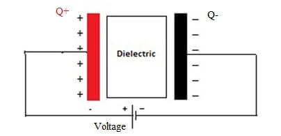
As shown in the figure below, it is clearly visible that the capacitor is usually constructed by using two or more parallel conductive plates which are separated from each other by an insulating material. This insulating material is known as Dielectric.
The conductive metal plates of a capacitor can be either of any shape like square, circular or rectangular, cylindrical or spherical depending on its application and voltage rating. When we supply DC voltage across a capacitor, Capacitor blocks the Dc current and allows the electrical charges to be present across the plates.
These charges are positive charges in the form of protons which got a deposit on one plate and negative charges in the form of electrons which got a deposit on the other plate. The basic formula of the parallel plate capacitor is:
C = ϵ0 A/D
Where A = Area of a capacitor
D= Distance between plates
ϵ0 = Permittivity of free space
As shown, Capacitance is directly proportional to the area of the plates and inversely proportional to the distance between the plates indicates that the more area of plates and less distance between them will result in high capacitance value. So before capacitor construction always considered these two factors.
Dielectric of capacitor
It is the most important factor which affects the overall capacitance of the device. For different results, we prefer different types of capacitors because they all have different dielectric material between their conducting plates.
The conducting plates of the capacitor are made up of metal foil allows the electrons to pass through it when it is excited by any power supply but the dielectric present between them obstructs the path of flow of electrons. The dielectric material is made up of a large number of insulating materials i.e. paper, mica, ceramic, etc.
Dielectric constant
The dielectric constant of material provides a measure of its effect on a capacitor. It basically increases the overall capacitance of the device which is affected by the dielectric material.
It is a dimensionless quantity relative to free space and it is preferred that a dielectric material with a high dielectric constant is a better insulator than a dielectric material with a lower dielectric constant.
The permittivity between the plates is equal to the product of the permittivity of free space (ϵ0) and the relative permittivity (ϵr) of the material being used as the dielectric and is given as:
ϵ = ϵ0 x ϵr
Capacitance Unit:
The capacitance of a capacitor is measured in Farads and is symbolized by F.
It is defined as being that a capacitor has the capacitance of one Farad when one coulomb of electric charge is stored in the conductor on the application of the one-volt potential difference.
Q = CV
Where Q: charge stored by the capacitor
C: Capacitance value of the capacitor
V: Voltage applied across the capacitor
How a capacitor works
When electric current starts flowing through the capacitor it got obstructs due to dielectric material present between the conducting plates of the capacitor. As a result, the charges got stuck to the plates of the capacitor.
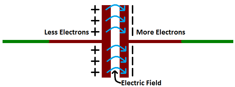
The negative charge in the form of electrons got deposited on the one plate of the capacitor and due to its large mass, it pushes away the like charges to the other plate making it positively charged in the form of protons.
As per the law, these opposite charges start attracting each other but when they come close to each other they got stuck on the plates forever due to dielectric present between them. The stationery charges on these plates create an electric field that influences electric potential difference and energy.
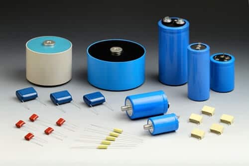
In market different types of capacitors is available, you have to select a suitable one for your work.
The basic phenomenon of a capacitor
(a) Charging:
When a capacitor is connected to a circuit with DC current source, the two processes occur namely charging and discharging the capacitor.
When the capacitor is connected to the DC supply and current starts flowing throw it then the charging of the capacitor begins. At the time of charging, both plates get positive and negative charges which further create the potential difference.
The capacitor is considered as fully charged when the voltage at the terminals of the capacitor is equal to the supplied voltage. When this happens the current automatically stops flowing through the circuit, indicates that the charging phase is over.
(b) Discharging:
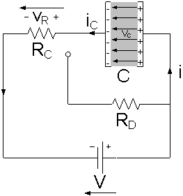
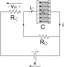
When the charging phase is finished, the capacitor act as an open circuit to direct current and resistance value tends to infinity. As shown in the figure below when the capacitor is disconnected from the power supply, the capacitor starts discharging through the resistor RD and the voltage between the plates drops down gradually to zero.
(c) Dielectric absorption
It is one of the factors which causes an error in applications based on charging and discharging of capacitors. Dielectric absorption also is known as soakage and was studied for more than one hundred years is a well-known phenomenon in capacitors which manifests as a slow recovery of a part of its lost voltage after the capacitor is completely discharged by shorting its terminals momentarily.
It has its origin in the polarization and depolarization processes occurring in the dielectric material during the charging of the capacitor. The amount of dielectric absorption depends upon the property of the dielectric material present between the conducting plates of the capacitor and the residual charges obtained in our measurements provide a direct quantitative measure of this effect.
Before buying always keep 7 things in mind like its Temperature coefficient, Polarization, Leakage current, etc. For detail read our detailed article capacitor buying guide
Calculations of Voltage, current, and charge:
Measurement of voltage and charge:
The easiest way to generate charge is to charge a capacitor. As it is well known, a Capacitor C is charged to voltage V is known to store a charge equivalent to:
Q = C x V
Where, Q = Charge in Coulombs,
C = Capacitance in Farads,
V = Voltage across the capacitor in Volts.
With the help of this equation, you can easily calculate charge and voltage with the known value of any of the two. Like with a known value of charge and capacitance you can easily calculate voltage or with a known value of voltage and capacitance, you can easily calculate the charge.
Current measurement:
The equation for calculating current through a capacitor is:
I = C dV/dt
The dV/dt part of that equation is a derivative of voltage over time. With a known value of voltage and capacitance, you can easily calculate current.
The big take away from this equation is that if the voltage is steady, the derivative is zero, which means the current is also zero. This is why current cannot flow through a capacitor holding a steady, DC voltage.
Capacitor Symbol and Units
Capacitor Symbol:
Its symbol consists of two parallel lines separated from each other i.e. Flat, curved or an arrow passes through it. The flat line indicates that the capacitor is non-polarized, the curved line indicates that it is polarized and arrow type indicates that it is of a variable type.
Capacitor marking:
Capacitors are marked in different ways depends upon its color code, voltage code, Tolerance code, and temperature coefficient, etc. Here we will explain the meaning and values of all such codes marked on different Types of capacitors.
Colour code:
Different schemes are used for different types of capacitors. Nowadays this type of capacitor marking is using less these days but it is available on some older components.
Tolerance code:
Some capacitors have tolerance code depends upon its dielectric material. The following tolerance rating is given below.
[supsystic-tables id=”1″]
Temperature coefficient:
On several capacitors marking or code indicates the temperature coefficient of a capacitor. All these codes are standardized by EIA (Electronics Industries Alliance), these codes are typically used for ceramic and film type capacitors.
[supsystic-tables id=”4″]
Voltage codes:
Working voltage is the key parameter of any electronic component. Sometimes capacitors are of smaller sizes and it is not possible to write whole code over it, so for this purpose, we write only one character.
This designates specific voltage values. Below we are providing a table that indicates the specific voltage values of the capacitor.
[supsystic-tables id=”5″]
Number code:
Most capacitors have a number printed on their body indicates their electrical properties. Capacitors like electrolytic are larger in size usually display the actual capacitance together with the unit like 120 µF while capacitors like ceramic are smaller in size use short notations of three numeric digit and letter where digit indicates the capacitance value in pF and letter indicates tolerance.
For example, let’s consider text 343M 220V available on the body of the capacitor. It designates 34 x 103 pF = 34 nF (±20%) with a working voltage of 220V. To prevent the risk of breaking down the dielectric layer always use the highest working voltage.
Applications:
Capacitors are widely used in the electronics industries. Following its application are:
- It is used in the coupling of two stages of a circuit.
- Used in filter networks.
- Used for smoothing the output of the power supply circuits.
- Used for delay application like in 555 timer IC controlling the charging and discharging.
- It is used for Phase alteration.
- In the camera flash circuits, it stores charges.
Hope you all like this article. For any suggestions please comment below. We always appreciate your suggestions.


What is the working of capacitors in celling fans?
Hi Ayush,
A ceiling fan uses a single phase induction motor to run it. This motor is NOT self-starting i.e. it requires an external force to run it at the time of starting. This property of the single induction motor is explained by the double field revolving theory.
To overcome this drawback, a capacitor is used. It is connected to a part of the winding in the fan motor. This creates a phase difference between the windings(one part with the capacitor connected and another part without the capacitor).
Thus, a field is produced which is resultant of the two fields. The rotor rotates according to the direction of the resultant field.
To increase the efficiency of the fan, the capacitor may be connected via. a centrifugal switch.
Very well said bro
Very good & brief explanation himanshi ji
Thanks, ritesh. We are glad that it is helpful to you. Like our page on fb and share with your friends. And if you have any doubt about the topic, ask in the comment section. ?