

In electronics, power amplifiers are categorized into various classes. These classes are based on the different characteristics of different power amplifier circuits. And Class A Amplifier is one of the simplest types of power amplifiers.
Though it is least used power amplifier, it is one of the most asked amplifier class in interviews and various competitive exams.
I have received many comments from our readers to write on this topic. So I decided to gather all of the knowledge I can and explain it in easiest way to my readers.
Here we are going to explain the efficiency equation, advantages, and disadvantages of class A amplifier in detail.
It has high fidelity and totally immune to crossover distortion. In the standard common emitter circuit configuration, the class-A amplifier uses the switching transistor.
In our previous article, we have explained the amplifiers theory, power amplifier circuit, diodes, rectifiers in detail.
Class A power Amplifier Theory:
Class A amplifier configuration is the simplest of all the power amplifier configuration because there is no switch off distortion to the output waveform even during the negative half of the cycle.
The transistor is always turned ON so that the output current flows for the entire cycle of the input waveform. To control the high load current. Class A amplifier may use a single power transistor or a pair of a transistor connected together.
Class A amplifier Collector Efficiency:
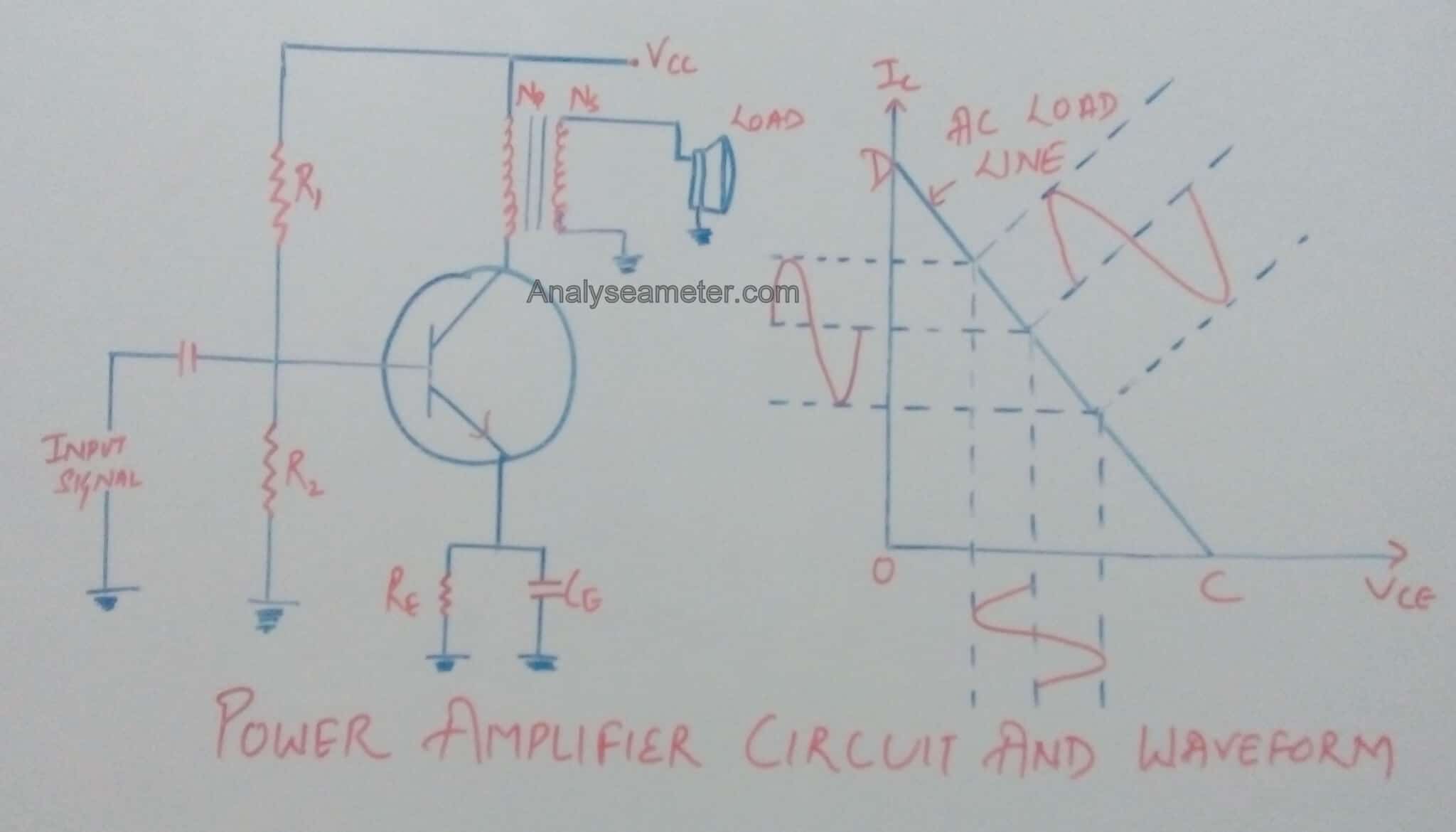
As shown in the circuit diagram below, a load is connected in the collector circuit either directly or through a coupling transformer.
Usually, the load is connected through an output transformer because it provides the perfect impedance matching. Because of the perfect impedance matching, maximum power can be transferred to the load while keeping the DC power loss minimum.
This all happens because of the small resistance of the transformer primary winding.
As we know, at zero signal conditions the effective resistance in the collector circuit is almost zero, since the primary winding resistance of the transformer is very small & can be neglected.
As shown in its waveform, a line passing through the Vcc & parallel to the axis of collector current Ic is known as the DC load line.
Draw the AC load line by cutting the DC load line at Q (operating point) such that Q lies at the center of the AC load line.
Calculation of Class A Amplifier Collector Efficiency:
To obtain maximum AC power output and hence maximum collector efficiency, the peak value of collector current due to signal alone should be equal to zero signal collector current.
When the positive half cycle is at its peak:
Total collector current =2 Ic
and,
Vce = 0
When the negative half cycle is at its peak:
Total collector current =0
and,
Vce = 2 Vcc
Therefore, Peak to peak emitter voltage is given as,
Vce (peak to peak) = 2 Vcc
Peak to peak collector current is given as,
Ic (peak to peak) = 2 Ic
= Vce (peak to peak) / RL
= 2 Vcc / RL’
where,
RL’ = Effective value of load resistance RL when referred to primary side.
i.e.
RL’ = n2 RL
As we know, DC power input and AC power output is given as,
Pdc = Vcc Ic = Ic2 RL’
Pac = [Vce (peak to peak) * Ic (peak to peak) ] / 8
= (2 Vcc * 2 Ic ) / 8
= 1/ 2 Vcc Ic
= 1/ 2 Ic2 RL’
Therefore, maximum collector efficiency is given by,
η max = (Pac / Pdc ) * 100
Substitute the value of DC power input and AC power output in the above equation, we get,
η max = [(Ic2 RL’) / 2 Ic2 RL’ ] * 100
η max = 50%
The above expression shows that in class A amplifier, maximum 50% of the DC power supplied can be converted into AC power output. Due to power loss in the primary of the transformer, the collector efficiency of class A amplifier is always less than 50%. It may be noted that maximum power is dissipated in the transistor in the zero signal condition i.e. given as,
Pdis = Vcc Ic
Note: Before selecting a transistor always remember that its power rating be >= Pdis.
You can learn more about class A amplifier from the video given below:
Video credit: Power devices and Circuits
Advantages and Disadvantages
In the electronics industry, we use power amplifiers for various purposes depending upon the requirement. Each and every amplifier has its own pros and cons as per its reliability and efficiency.
Advantages of Class A amplifier:
As we have read above, there are many advantages of using class A amplifier over other types of amplifiers. Some of them are mentioned below:
- It has high fidelity because at the output exact replica of an input signal is produced.
- Its Designing is simple.
- It has improved high-frequency response because the active device is On full time i.e no time is required to turn-on the device.
- There is no crossover distortion because the active device conducts for the entire cycle of the input signal.
- Single ended configuration can be easily & practically realized in class A amp.
Disadvantages of Class A amplifier:
Though there are many advantages but because it is an electrical component, it has some demerits or disadvantages too. These are listed below:
- Due to the large power supply and heat sink, class A amp is costly and bulky.
- It has Poor Efficiency.
- Due to the transformer coupling frequency response is not good.
Hope you all like this article. For any suggestions please comment below. We always appreciate your suggestions.