

The amplifier is one of the devices in electronics that are used in majorly every device. It is mainly used in devices that need signal amplification like audio, and power signals, etc. According to the output signal, it is categorized into 3 categories.
In this article, we are going to discuss the definition, working, diagram, gain, efficiency, classification, etc in detail.
What is Amplifier: Definition
An amplifier is an electronic circuit used to boost up the strength of the weak signal. This signal can be a current, voltage or power signal. It is a 2 port circuit that increases the amplitude of the input signal and provides an amplified signal at the output end.
The process of boosting an electrical signal is called Amplification. The amplification is measured by its gain. It can either be a separate piece of equipment or an electrical circuit within another device.
Without changing other parameters of the waveform such as frequency or wave shape, an amplifier increases the amplitude of a signal waveform. But it is not as simple as we think.
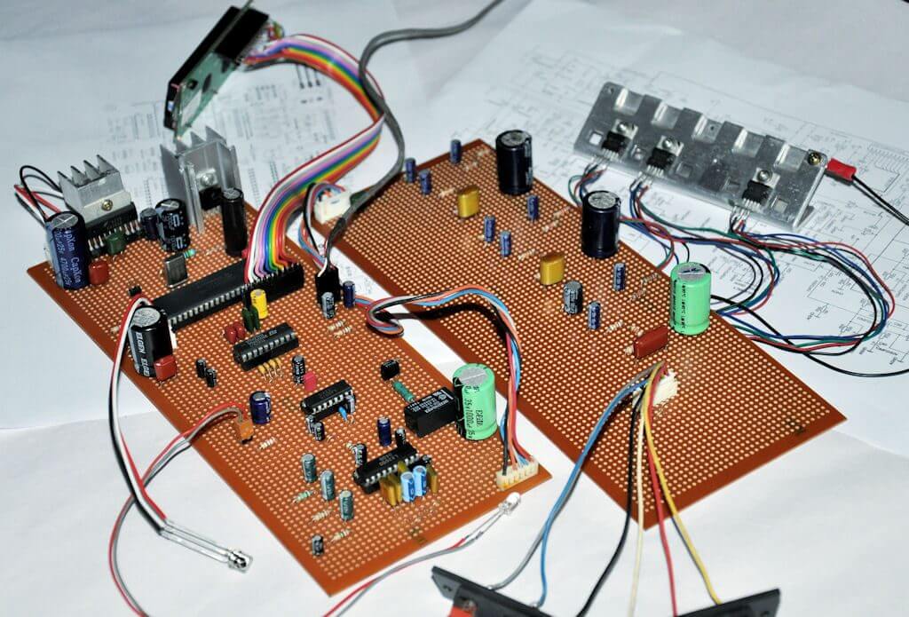
The above circuit board is of an audio amplifier. It will amplify the audio signal in the device such as radio, television, etc. And you can see there are many components added in making of it.
So before we go in advance topics, let’s start with some of the basics.
Block diagram
In all practical amplifiers, a number of stages are cascaded to amplify a weak signal to a sufficient level to operate the output device.
Here we are taking an example of a loudspeaker. Here we will modulate the strength of the voice so it is voice amplification. The primary function of the first few stages is only to amplify the input signal and the last stage is designed to drive the output device.
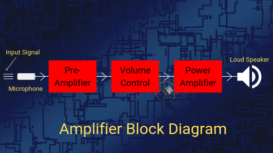
As shown in the block diagram above, in a public address system when a person speaks into a microphone, it converts the sound waves into electrical signals. If we directly fed this signal to the speaker, it will not be in a position to drive the speaker. Because the electrical signal so produced is of very low voltage.
Due to this reason, the voltage level of the signal is first raised to a sufficient level by passing it through a number of stages of the voltage amplifiers. This amplified voltage signal is then fed to the final stage of the amplifier to deliver the required power to drive the speaker.
Finally, after this stage, the loudspeaker converts the electrical signals into sound waves (loudspeaker output). Therefore, a large number of people will be able to hear the speech.
Amplifier Circuit
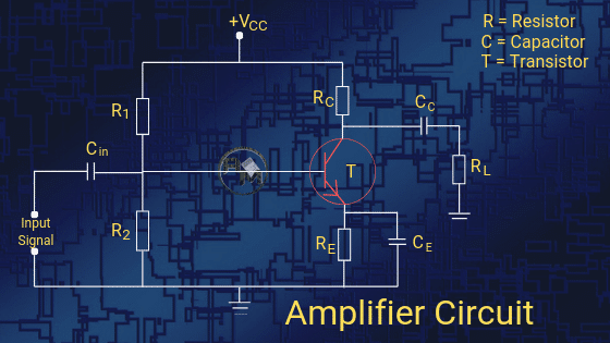
Given above is a circuit diagram of a transistor amplifier. It comprises resistors, capacitors, and transistors. R1, R2, and RE form biasing and stabilization circuits. RC is a collector resistance, RE is emitter resistance. Similarly, Cin and CC are input capacitor and Collector capacitor respectively.
VCC is voltage to the collector. For detail study, you can go through our article transistor as an amplifier.
Amplifier Gain
The measurement of amplification is represented by Gain. Basically, it means how much amplification of the signal we have gained in the process.
It is defined as the ratio of the output signal (voltage or current) to the input signal (voltage or current). It can be said to be the relationship that exists between the signal measured at the output to the signal measured at the input.
For amplification, it is designated by the symbol A and has no unit. Though it can be measured in Decible represented by dB.
Depending upon the quantity being measured, you can calculate the Gain in three ways.
(i) Voltage Gain:
It is defined as the ratio of the output voltage to the input voltage. Its equation is given as:
Voltage gain (AV) = Vout / Vin
(ii) Current Gain:
It is defined as the ratio of the output current to the input current. Its equation is given as:
Current Gain (Ai) = Iout / Iin
(iii) Power Gain:
It is defined as the product of the voltage gain and current gain.
Power Gain (Ap) = AV * Ai
Note: For Power gain you can also divide the power obtained at the output with the power at the input end.
Gain can also be calculated in terms of decibels. The expression for calculating gain is given as:
Voltage gain in dB (av) = 20 log AV
Current gain in dB (ai) = 20 log Ai
Power gain in dB (ap) = 10 log Ap
Amplifier Efficiency
The efficiency is defined as the ratio of output power collected at the load to the input power given to the circuit. It is represented as η (eta). It has no unit.
Efficiency (η) = (output power)/(input power) x 100
For example, suppose we give 50W power to the circuit but the output signal has 30W power only. That means the efficiency of that device will be, η= (30/50) x 100= 60%.
Types of Amplifiers
There are many types of amplifiers depending on the frequency range they work in and the type of signal they amplify. Primary amplifier types are listed below:
- Audio Frequency Amplifier
- Intermediate Frequency Amplifier
- R.F. Amplifier
- Ultrasonic Amplifier
- Wideband Amplifier
- DC Amplifier
- Video Amplifier
- Buffer Amplifier
- Operational Amplifier (Op-amps)
- Transistor Amplifier
Classification of Amplifiers
As we know from the above circuit diagram, an amplifier contains amplifying components such as a transistor, Field Effect Transistor, etc. It has two input terminals and two output terminals with the output signal being much greater than that of the input signal.
These can be classified according to the output we get at the load. The classification is as follows:
(i) Current Amplifier:
This is used to amplify the current signal. The current signal gets modulated hence the amplitude of the current signal at the load(output) terminal will be greater than the amplitude of the current signal at the input terminal.
(ii) Voltage Amplifier:
These are designed to achieve maximum voltage amplification because it raises the voltage level of the signal at the beginning. The voltage gain of the amplifier is given by the expression:
AV = β * (Rc / Rin)
In such amplifiers, the following features are required to be incorporated to perform well. The points to be noted are:
- High Collector load resistance ( Rc): The collector load resistance should be relatively high. To obtain this condition we keep the lower collector current i.e. 1 mA.
- Higher Value of β: The transistor used should have a higher value of β i.e. greater than 100. Hence, the transistor should have a thin base.
- R-C coupling: An RC coupling has a smaller size, smaller weight, lower cost and occupies less space. Therefore, it is preferred to couple various stages of voltages amplifiers by this coupling method.
- Low input resistance ( Rin ): The input resistance of the transistor is quite low.
(iii) Power Amplifier:
To handle a large amount of voltage and current at the load, a power amplifier is used to deliver a larger amount of power to the load. This is because the product of voltage and current at the output is greater than the product of voltage and current at the input. To meet these requirements, the following features are to be kept in mind:
- The Larger size of transistor: When heavy current passes through the transistor, more heat is produced at the collector junction. To dissipate the heat produced, a larger size of transistors are required.
- Thicker base: Base of the transistor is thick because the transistor employed has to handle the larger current.
- Low collector load resistance ( Rc): The collector load resistance should be of smaller value because if it has high value there will be more power loss in the resistor.
- Transformer Coupling: To transfer maximum power to the output device we have to maintain input impedance equal to the output impedance. To match the impedance of the loudspeaker to the output impedance of the amplifier, a transformer is employed at the output.
Comparison between Voltage and Power amplifiers:
The comparison between power and voltage amplifiers on the basis of coupling, collector current, output impedance, input voltage, output power, etc is given below in the tabular form.
[su_table responsive=”yes”]
| Amplifier Properties | Power Amplifier | Voltage Amplifier |
| Input Voltage | High | Low |
| Collector current | Very high | Low |
| Output Power | Very high | Low |
| Output Impedance | Low | High |
| Coupling | Invariably Transformer coupling | RC Coupling |
| Collector Load Resistance (Rc) | Low | High |
| Current amplification (β) | Low | High |
[/su_table]
Hope you all like this article. For any suggestions please comment below. We always appreciate your suggestions.
3 Comments