

We have covered the basics of Rectifier and its types in our previous article. Now we will learn about each type of rectifier individually. In this article, we will cover all about half wave rectifier.
As we have read that there are mainly three types of rectifiers, namely half wave, full wave, and center tapped. This classification is done keeping in mind whether it uses full AC voltage waveform or half. Keep this point in mind while going through the rest of the article.
What is Half Wave Rectifier?
Half Wave Rectifier Definition can be given as:
A Half wave rectifier is the type of AC to DC converter that rectifies only one-half cycle of the input AC waveform i.e. either positive or negative cycle.
It is nothing more than a single pn junction diode connected in series to the load resistor. To rectify the signal these rectifiers are used in the AM radios.
To understand the basic theory of half wave rectifier, you must know rectifier operation, circuit, etc. Here we discuss one by one in brief.
Half-wave Rectifier Circuit
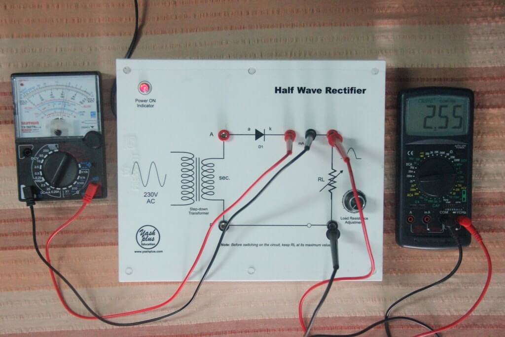
The circuit is shown in the figure below. In half wave rectifier, a transformer and a single diode are used for the rectification of AC voltage.
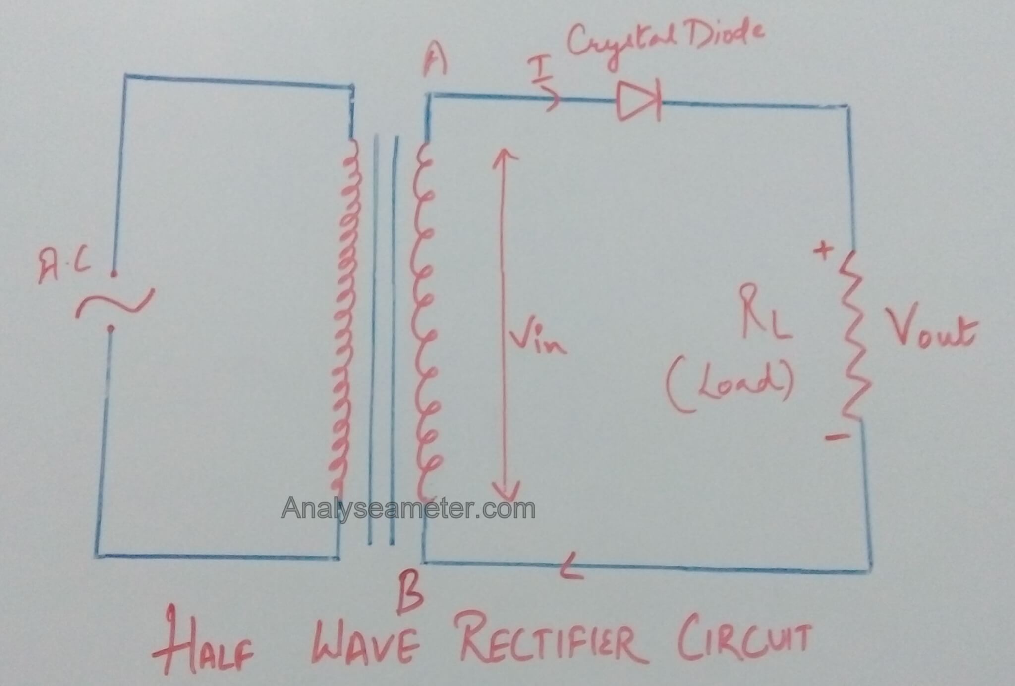
For half-wave rectification, only one crystal diode is used.
As shown in Figure above, we supply alternating current as an input which generally gets rectified through a transformer. The transformer is used to step-up or step-down the mains supply voltage as per requirement.
At the anode side of the diode, the transformer is connected while at the cathode side load resistance is connected.
The main purpose of the transformer is to isolate the rectifier circuit from power lines to obtain the desired level of dc voltage and reduces the risk of electric shock.
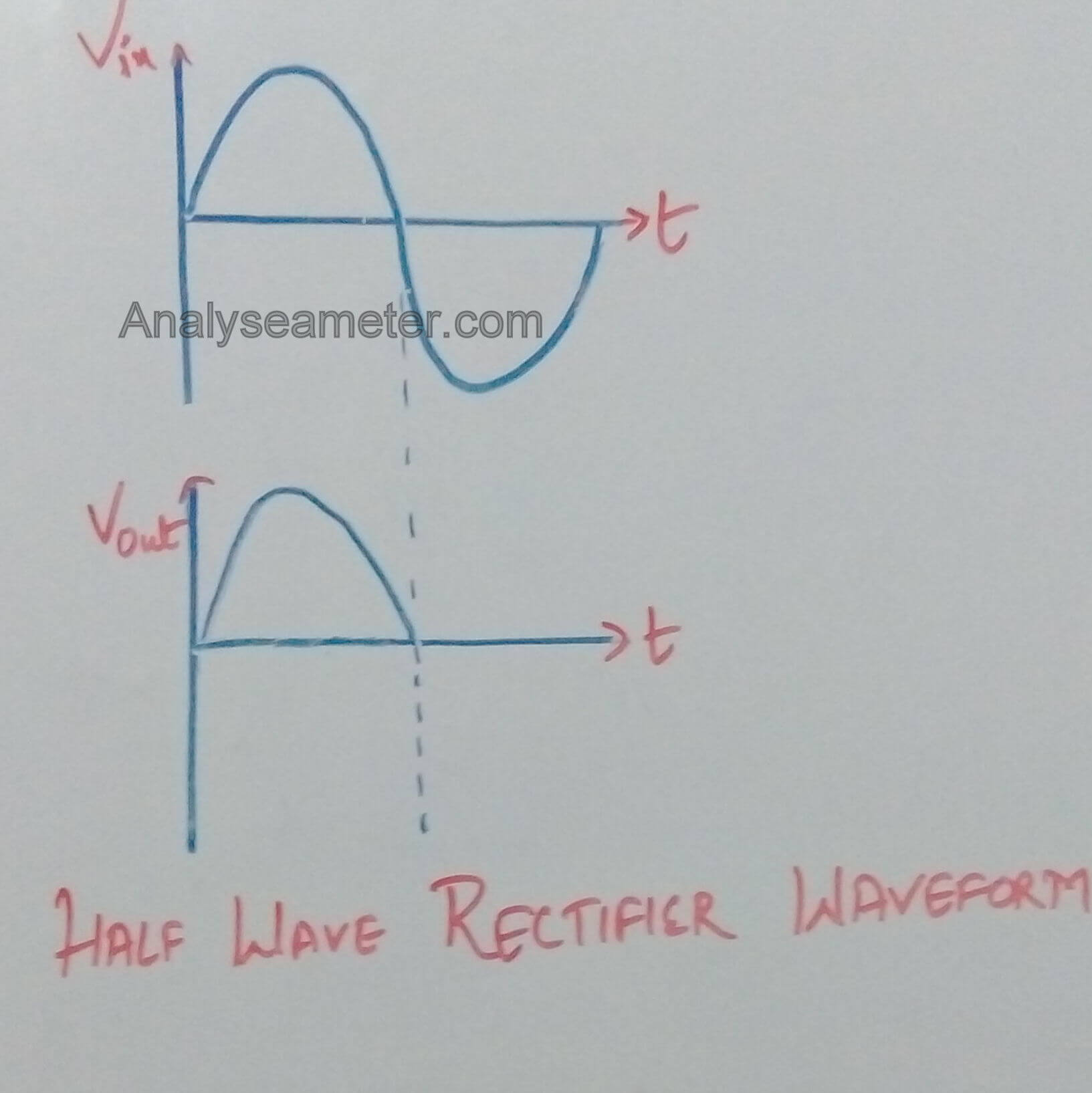
The final obtained DC voltage signal is shown in the below figure.
Working Principle
The working principle of Half wave rectifier is quite simple i.e convert alternating current to direct current.
The reduced voltage is fed to the diode and load resistance and the input voltage is stepped down using a transformer.
The diode will be forward biased during the positive half cycle of the input wave while it is reversed biased during the negative half cycle of the input wave.
Across the load resistor, the output is taken out indicates that the diode passes current only during the one-half cycle of the input wave. During the positive half cycle, the output is positive & significant while during the negative half cycle output is zero & insignificant.
Half wave rectifier Operation
As shown in the figure above, the half wave rectifier circuit comprises a semiconductor diode with a load resistance RL. The diode is connected in series with the secondary of the transformer and the load resistance while AC supply main connected to the primary of the transformer. It basically works in two cycles; a positive and a negative cycle of AC voltage.
Let us see how it works in both cycles.
Positive Half cycle:

When AC supply is switched on, the alternating voltage Vin starts appearing across the terminals AB at the secondary winding of the transformer.
During the positive half cycle, the crystal diode is forward biased making the terminal A positive w.r.t the terminal B. Therefore, it conducts and current flows through the load resistor.
As shown in the waveform diagram, the current varies in magnitude and shows output during the positive half cycle.
Negative Half Cycle

During the negative half-cycle, the crystal diode is reversed biased making the terminal A negative w.r.t terminal B. Under this condition, the diode does not conduct and no current flows through the circuit.
Therefore, in the negative half cycle of the input voltage, no voltage appears across the load resistor.
Characteristics and Properties
For the analysis of half wave rectifier following parameters or properties are considered.
[irp posts=”1187″ name=”Half Wave Rectifier Efficiency Equation and Applications”]
Ripple Factor of Half Wave Rectifier:
Ripple Factor is defined as the ratio of the effective value of the AC components of current or voltage present in the output from the rectifier to the dc component in output voltage. Simply, it is a measure of remaining alternating components present in the rectifier output.
Calculation of Ripple factor:
The effective value of ripple factor can be calculated as given below. The effective of load current is given as,
I2 =I2dc +I21+I22+I24
= I2dc +I2ac
Where I1, I2, I4 are the RMS values of the second, fourth and so on harmonics.
Ripple factor (γ) is given as follows;
γ = Iac / Idc
= (I2 – I2dc)/ Idc
= {( Irms/ Idc2)-1}
= Kf2 – 1
where Kf is the form factor of the input voltage. For half wave rectifier form factor is calculated as:
Kf = Irms /Iavg
= (Imax/2)/ (Imax/π)
= π/2 = 1.57 ( π = 3.14)
As we know,
Ripple factor = Kf2 – 1
= (1.57 * 1.57) – 1
= 1.21
Peak Inverse Voltage
Peak inverse voltage is defined as the maximum value of the voltage coming out of the diode when it is reverse biased during the negative half cycle. The diode used must have higher PIV rating than the voltage which is coming across it.
Transformer Utilization Factor
It is defined as the ratio of power delivered to load and VA rating of the transformer. Half wave rectifier has TUF of around 0.287.
Note: 1 / TUF signifies that the transformer must be 1.23 times higher then that when it is used to deliver power from a pure AC voltage.
Regulation
Regulation is defined as the ratio of the percentage of the difference between the no-load voltage & full load voltage to full load voltage. It is given as:
% Regulation = {(Vno-load – Vfull-load)/ Vfull-load}* 100
Note: For an ideal power supply, the output voltage should be independent of load current and the percent regulation is equal to zero.
Efficiency
It is defined as the ratio of the DC power output to the AC power input. Mathematically, it is given as:
η = DC Power Output / AC power input
where η = Rectifier Efficiency.
The Efficiency of Half wave rectifier is 40.6% only due to the fact that it rectifies or converts only one cycle of the input waveform.
You can also watch the video by All About Circuits
Advantages of Half Wave rectifier:
- It is cheap because it requires fewer components.
- It is simple and easy to construct.
Note: Due to high ripple factor, half wave rectifier is rarely used in practice because high ripple factor will result in noises in input audio signal.
Disadvantages of Half wave rectifier:
- The output is low because the AC supply delivers power only half the time.
- The output signal contains more alternating components, therefore, it needs heavy filter circuit to smooth out the output.
- It has low transformer utilization factor.
- Hysteresis losses and harmonics occur due to DC saturation of the transformer core.
Hope you all like this article. For any suggestions please comment below. We always appreciate your suggestions.
Very useful tutorial. thank you