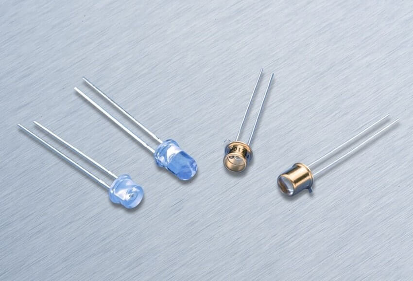
Photodiode is a special kind of diode convert light energy into current or voltage. It can be used to detect the presence or absence of minute quantities of light and can be calibrated very accurate for measurements.
In our previous articles, we explain about LED diode, Zener Diode, P-n junction diode etc. Here we are going to explain Photodiode operation, working principle, modes etc in detail.
These may be either exposed or packaged with an optical fiber connection or window to allow light to reach the sensitive part of the device. It may contain in-built lenses, optical filters and frequently uses photodetectors which have largely replaced the phototubes.
Photodiode Working Principle:
Photodiode is a semiconductor device commonly known as PIN photodiode consists of an active p-n junction which operates in reverse bias. When an electric field is applied across the junction then the electrons and hole starts moving towards it and got recombine in the depletion region. After recombination, light absorbed in the depletion region generates electron-hole pair, most of which contributes to the photocurrent. The photocurrent thus generated is proportional to the absorbed light intensity. The intensity of photon or packets of light absorption depends on the energy of photon i.e. lower the energy of photons, the deeper the absorption. To make the external current flow through the circuit, the two terminals of diodes are electrically connected. Before reaching the junction field if the created minority carriers of that region recombine with the bulk carriers of that region, the carriers are lost and no external current flows. The total current passes through the photodiode is the sum of the photocurrent and dark current which flow with or without light. By minimizing the dark current the sensitivity of the device can be increased.
Photodiode Equivalent Circuit:
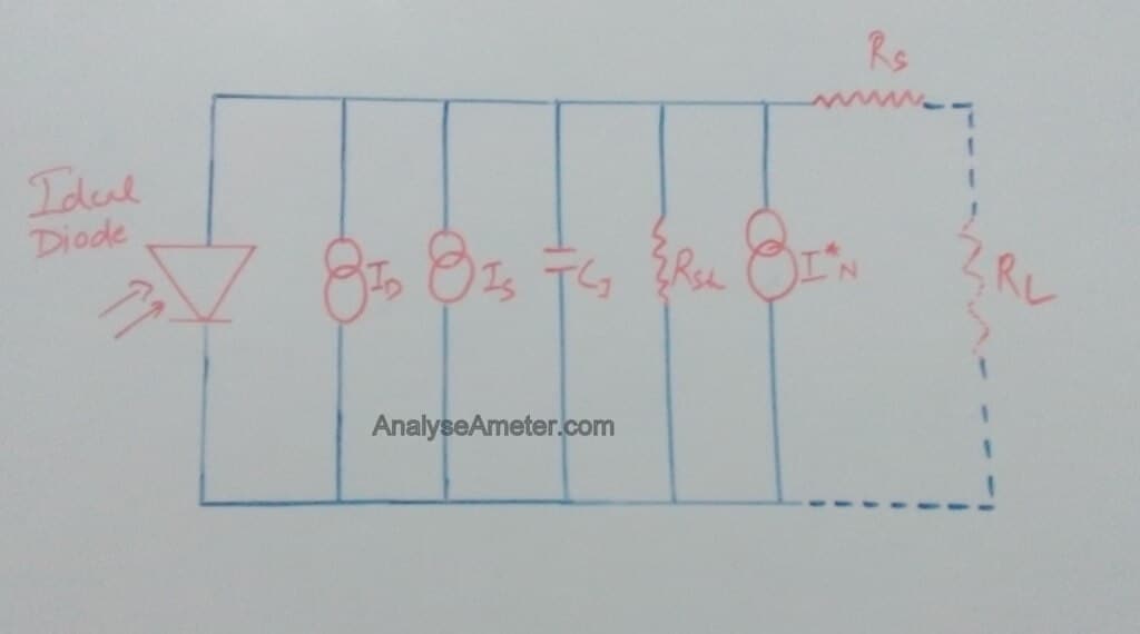
The equivalent circuit of the photodiode is shown in the figure above. When illuminated this diode behave as a purely current source. When operated without bias, this current is distributed between the external load resistor and the internal shunt resistance. During this mode, a voltage develops will create a forward bias which reduces its ability to remain a constant current source. It becomes an ideal current source only when it is operated with a reverse voltage bias.
The component shown in the figure is abbreviated as:
Rsh = Shunt resistance in ohms.
Id = Dark current in Amperes.
Is = Light signal current in Amperes.
R = Photodiode responsivity in Amperes/Watt.
C = Junction capacitance in Farads.
Rs = Series resistance in ohms.
RL = Load resistance in ohms.
I* n = noise current in Amperes.
Po = Incident power in watts.
Photodiode Operation:
Photodiode operation is based on a mechanism known as the photoelectric effect, which creates electron-hole pair when a photon of sufficient energy strikes the diode. Depending on the application-specific requirement, the photodiode can be operated with or without an applied reverse bias. It can be operated in different modes.
(i) Photovoltaic mode:
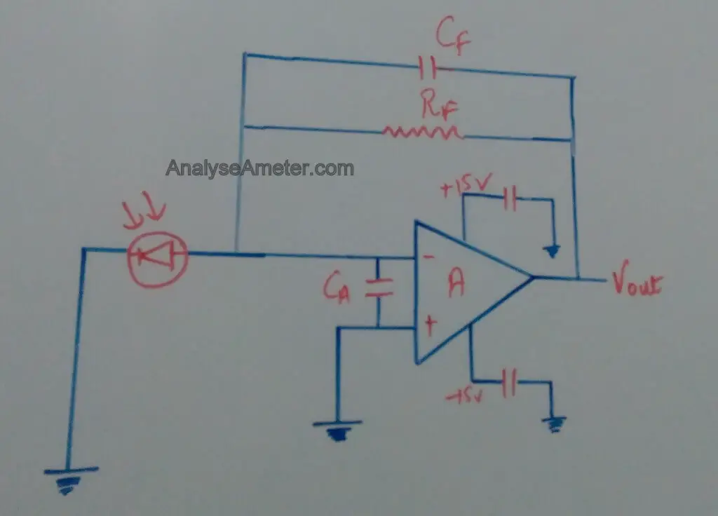
When a photodiode is used in low-frequency applications as well as ultra low-level light application this mode of operation is preferred. It is also known as the zero bias mode into which a voltage is generated by the illuminated photodiode. When we configured photodiode with op amp the photocurrents in this mode have less variation in responsitivity with temperature. The diagram of a photovoltaic mode of operation is given below.
As shown above, the photodiode is connected to the FET input operational amplifier inverting terminal. The detector is unbiased to eliminate any additional noise current. The output voltage and the op amp noise current is determined by the equation given below:
Vout = Ip * Rf
In * [ Arms / √Hz] = √ 4KT / Rf
Where K = 1.38 * 10 -23 J/K and T is the temperature in Kelvin.
(ii) Photoconductive Mode:
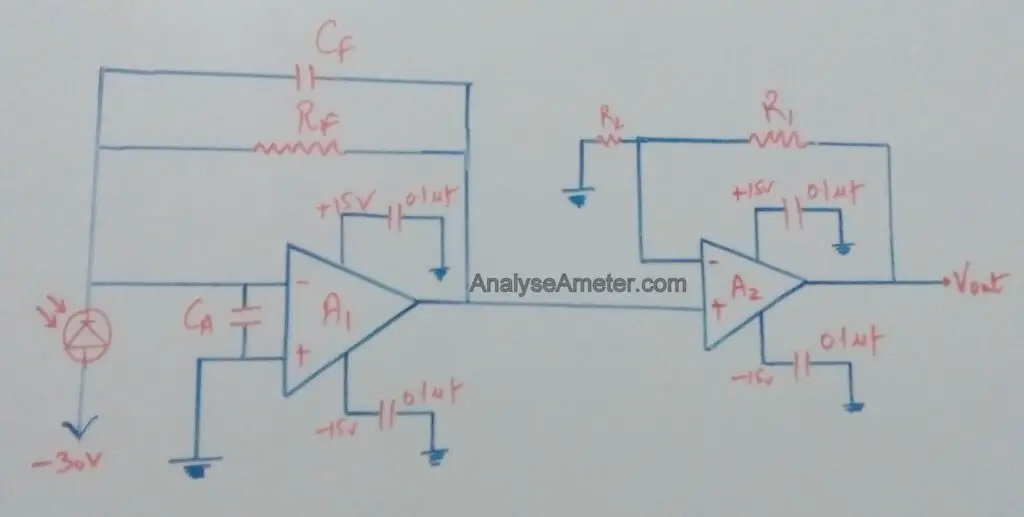
In this mode the diode is reverse biased. The reverse voltage increases the width of the depletion layer, which in turn reduces the response time and capacitance of the junction. Applying reverse bias will increase the noise and dark current. The diagram of a Photoconductive mode of operation using operational amplifier is given below.
As shown above, in this configuration the detector is biased to reduce junction capacitance thus reducing noise and rise time. A two-stage amplification is used in this diagram includes a non-inverting amplifier for voltage amplification and trans impedance pre-amp for current to voltage conversion. The gain and bandwidth are directly determined by the given equation as shown below:
Gain = Vout / P = Rf ( 1 + R1 /R2) Rλ
f (Hz) = √ GBP / (2∏ Rf (Cj + Cf + Ca)
where GBP is the gain bandwidth product and Ca is the amplifier input capacitance.
(iii) Avalanche Diode Mode:
In this mode, avalanche photodiode is operated in a high reverse bias condition which allows the multiplication of an avalanche breakdown to each photo-generated electron pair which resulting in internal gain within the diode.
Photodiode Applications:
Due to increasing demand of photodiodes in electronics industry, it becomes most versatile and efficient diode. Following of its field of applications are:
- It is used in medical industry such as detectors for computed tomography and pulse oximeters.
- It is used in consumer electronic devices such as receivers for infrared control devices, smoke detectors, compact disc players etc.
- It is used in science industry for accurate measurement of light intensity.
- It is used to generate an output which depends upon the illumination.
- It is used in optical communication devices and Automotive devices.
- It is used in bar code scanners and position sensors.
Hope you all like this article. For any suggestions please comment below. We always appreciate your suggestions.


Wow! In the end I got a webpage from where I can genuinely get helpful information concerning my study and knowledge.