

Fluke 1507 insulation resistance tester is a great test tool which makes maintenance test more thorough and troubleshooting more effective. Before performing measurements using this tester, it is recommended to go through Fluke 150x series insulation resistance tester introduction to enhance more knowledge regarding this tester.
How to measure voltage using Fluke 1507 insulation resistance tester?
Steps for measuring voltage are:
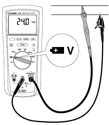
- Insert the test probes into V insulation and COM terminals.
- Turn the rotary switch to V/
 labelled function.
 - Select the voltage ranges from 0.1V to 600V as per your need.
- Short the ends of the probe by connecting it to the battery for Dc voltage or to any switch for Ac voltage.
- By connecting the probes, the output voltage should start appear on the display of the tester.
- Note the measurement display on the screen. When you have noted the readings, remove the probes safely to avoid any electrical shock or damage to the device.
- Set up for measurement of AC & DC voltage are shown below in the figure.
How to measure Earth bond resistance using Fluke 1507 insulation resistance tester?
Always perform resistance tests on de-energised circuits because it will adversely effect the device under test.
Steps for measuring Earth bond resistance are:
- Insert test probes in the Ω and COM input terminals.
- Turn the rotary switch to the Zero Ω labelled function.
- Press the blue coloured button after shorting the ends of the probes together and wait until dashes appear on the display.
- The insulation tester now starts measuring the probe resistance, stores the reading in memory and subtracts it from the final readings.
- You can save the probe resistance reading even when the Tester is turned off but if the probe resistance is greater than 2Ω, the resistance will not be saved.
- Connect the probes to the circuit to be measured. The tester automatically detects if the circuit is energised or not by considering these conditions:
- The display shows —- until you press the Test labelled button and a valid resistance reading is obtained.
- If the voltage is greater than 2V then the primary display warns by showing the high voltage symbol. In this condition, the test is inhibited and it is recommended to disconnect the tester and remove the power before proceeding.
- When you press the TEST labelled button if the tester chirps indicate that the test is inhibited because the voltage is present at the probes.
- To start the test press and hold the TEST labelled button. The TEST labelled icon appears on the lower portion of the display until you release the TEST labelled button.
- The resistance reading starts appear on the screen and remains on the display until new the test is started.

Note: When resistance is higher than the maximum display range, the Tester displays the > symbol and the maximum resistance for the range.
How to measure Insulation resistance using Fluke 1507 insulation resistance tester?
Steps for measuring insulation resistance are:
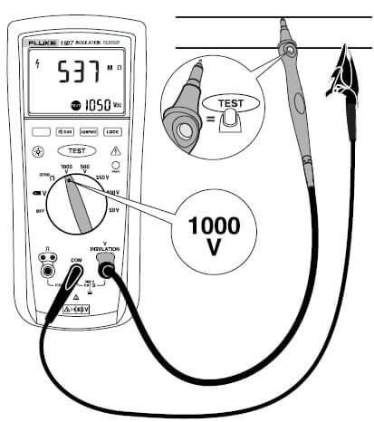
- Insert test probes in the Ω and the COM input terminals.
- Turn the rotary switch to the desired test voltage.
- Connect the probes to the circuit to be measured. The tester automatically detects if the circuit is energised or not by considering these conditions:
- The display shows —- until you press the Test labelled button and a valid resistance reading is obtained.
- If the voltage is greater than 30V then the primary display warns by showing the high voltage symbol. In this condition, the test is inhibited and it is recommended to disconnect the tester and remove the power before proceeding.
- When you press the TEST labelled button, if the tester chirps indicate that the test is inhibited because the voltage is present at the probes.
- To start the test, press and hold the TEST labelled button. The secondary display shows the test voltage applied to the circuit under test.
- The high voltage symbol along with a primary display shows the resistance in the MΩ or GΩ. Until TEST labelled button is released the test name icon will appear on the lower portion of the display.
- Keep the probe on the test points and release the TEST labelled button. The circuit under test then discharges through the tester.
What is polarization Index and Dielectric absorption ratio and how to measure it with Fluke 1507 insulation resistance tester?
Polarization Index is the ratio of the 10-minute insulation resistance to the 1-minute insulation resistance while Dielectric Absorption Ratio (DAR) is the ratio of the 1-minute insulation resistance to the 30-second insulation.
Insulation tests should only be performed on de-energised circuits. Now for its measurement we have to follow these steps given below:
- Insert test probes in the Ω and the COM input terminals.
- Turn the rotary switch to the desired test voltage.
- To select polarisation Index or dielectric absorption ratio, press the PI/DAR labelled button.
- Connect the probes to the circuit to be measured. The tester automatically detects if the circuit is energised or not by considering these conditions:
- The display shows —- until you press the Test labelled button and a valid resistance reading is obtained.
- If the voltage is greater than 30V then the primary display warns by showing the high voltage symbol. In this condition, the test is inhibited and it is recommended to disconnect the tester and remove the power before proceeding.
- When you press the TEST labelled button, if the tester chirps indicate that the test is inhibited because the voltage is present at the probes.
- To start the test, press and hold the TEST labelled button. The secondary display shows the test voltage applied to the circuit under test.
- The high voltage symbol along with a primary display shows the resistance in the MΩ or GΩ. Until TEST labelled button is released the test name icon will appear on the lower portion of the display.
- When the test is completed, the PI or DAR value is displayed on the primary display.
Hope you all like this article.For any suggestions or query please comment below.We always appreciate your suggestions.
Great article review sharing FLUKE 1507. I have enjoyed Fluke products continuously from my first appearance to them in the U.S. Navy over 25 years ago to my new job in under electrical mining work. I love FLUKE brand.