

The press tool ( commonly known as die/ dies) is an assembly of die, punch, punch plate, punch backplate, stripper plate, etc. to produce sheet metal components/ stamped parts from the flat metal sheet.
For More information on press tools read our detailed article on sheet metal stamping.
 Press Working Terminology
Before designing the sheet metal stamping process Press tool, it is necessary to understand the configuration and components of the press tool. The press tool consists of Punch/ Punches, Die, Punch Plate, Backup plate, Stripper, ejectors many more components. To better understand the main components of the press and dies, just have a look at the given figure.

Ram ( Slide): Moving Component of the press which transfers the mechanical or hydraulic force from the Flywheel /hydraulic system to the Press tool for sheet metal stamping.
Shank: The shank is used as a part for installing the top die in the slide of the press machine.
Punch Holder ( Upper Shoe): This is the upper part of the die set which contains guidepost pushing. The whole upper section (generally contains Punch, punch plate) of the die set is mounted on the upper shoe.
Die Holder ( Lower Shoe ): This is the lower part of the die set which contains guidepost. The whole lower section ( Generally contain die, stripper) of the die set is mounted on the upper shoe.
Back up Plate: Backup plate is placed so that the intensity of pressure does not become excessive on the punch holder. It is also called Punch backplate and Pressure Plate.
Punch Plate: The function of the punch plate is to hold punch in its proper relative position. The punch plate fits closely over the body of the punch. It is also called Punch Retainer.
Punch: This is the main component of die assembly, which is directly or indirectly moved by press ram or slide. Punch and die act together to make a stamped part.
Bed: The bed is the lower part of the press frame that serves as a table to which a bolster plate is mounted.
Bolster Plate: This is a thick plate secured to the bed which is used for supporting & locating the die set.
Die: Die is a female part of the die block/press tool for producing the given job work in a press. Die and punch work together to make the desired shape product.
Stripper: A stripper is used to strip the metal strip from a punch or die.
Guidepost & Guide post bushing: This two-component of the press tool guide the die set to maintain the alignment during the operation. Properly lubricated, and positioned, they improve tool operation and contribute to producing quality products. This is also called a pillar die set.
Shut Height: The distance between the top of the bed and bottom of the slide, with its stroke down and adjustment up.
Stroke: The distance of Ram movement from its up position to its down position. It is generally constant for mechanical presses but variable for hydraulic presses.
Metal stamping Press Tools Components
Press Tool components may be divided into the following categories:
- Structural Components
- Working Components
- Guiding or Locating Components
- Stripping Components
- Fastening Components
- Feeding Components
Structural Components
Press tool Components holding working components to one another and the press. Like Upper shoe, Lower shoe, shank.
Working Components
Components which actually participate in forming the desired shape stamped part. Like Punch & Die.
Guiding or Locating Components
Guiding Components maintain accurate alignment of the upper shoe with the lower shoe during the operation. Guidepost sets and dowel pins are examples of guiding components.
Stripping Components
components that remove or strip blanks and scrap from the punch or die when the operation is over. Like Stripper, push off pins, Ejectors, Knockouts.
Fastening Components
Fastening Components hold together all parts of the press tool as a unit. Like Punch Plate, Die block, All Fasteners.
Feeding Components
Feeding Components feed the blank or metal sheet to the stamping station. These components help to increase the rate of production.
The Requirement of Press Tool Design
While designing a press tool and selecting the press for a given job, the following factors must be considered :
- Thickness of component
- Power requirement
- Kind of operation to be performed
- No. of operations to be performed
- Overall work size
- Speed of operation.
Press tool design should suit the type of production i.e mass production, small-batch, or Huge batch. Press tools should meet the following requirements:
- The press tools should ensure the demanded output, safe operation & easy maintenance.
- Press tools should be designed in such a way that possible standard components are used for the manufacturing of products.
- Press tools should be designed for maximum utilization of material as well as manpower.
- Working Parts of the press tools must be strong and durable and replaceable when worn out.
- Dimensional accuracy and surface finish must be within tolerances.
Design of Press Tools
The sheet metal stamping process is a very fast and precise manufacturing process. But what if, press tool is not working efficiently or it takes many more operations to produce stamped parts. So it is very important to design an economy friendly and time-saving press tools.
Steps to design any Sheet metal stamping press tool or die.
- The computing of the required force ( Press tonnage)
- Selection of press
- Determination of shut height of the tool
- computing die thickness and margins ( Minimum cross-section)
- Drawing strip layout and comparing material utilization
- Design of locating elements
- Selection of Hardware
- Drawing die plan ( Pillar sets, Punch height, and mounting)
- Identify the center of pressure and checking scrap disposal
- Drawing Details
What is Strip Layout?

The material economy is very important in the sheet metal stamping process. Since the blanking is the first operation, the raw material economy may be affected by using the most economical strip layout which can give the highest utilization of the material. Generally, press tools designers draw at least five strip layouts for computing and compare their material utilization before designing the press tool.

Strip layout for Blanks shaped like letters L, T or U may be produced economically by inverted layouts as shown in the following image.
The material utilization for strip layout may be calculated from the following formula –
Material Utilization = (Area of blanks from the metal strip/ Area of strip before blanking)
OR
Material Utilization = (Weight of blanks/ Weight of strip before blanking)
Theory of Press Tool Stamping Process

Sheet metal cutting operations in a stamping work is a shearing process. As the punch touches the sheet metal and travels downwards, it pushes the material into the die opening. The material is subjected to both compressive and tensile stresses. These stresses will be highest at the edges of the die and punch and material will stressing beyond its elastic limit and start cracking there.
3 Steps of shearing or fracture in sheet metal cutting operations.
- Stressing the material beyond its elastic limit.
- Plastic deformation due to reduction in area
- fracturing starts in a reduced area.
Forces Disposition
The forces developed in the shearing operation is represented by a triangle as shown in the below-given figure. The vertical shearing force and horizontal lateral force are represented by V and H respectively. The resultant force is represented by R.
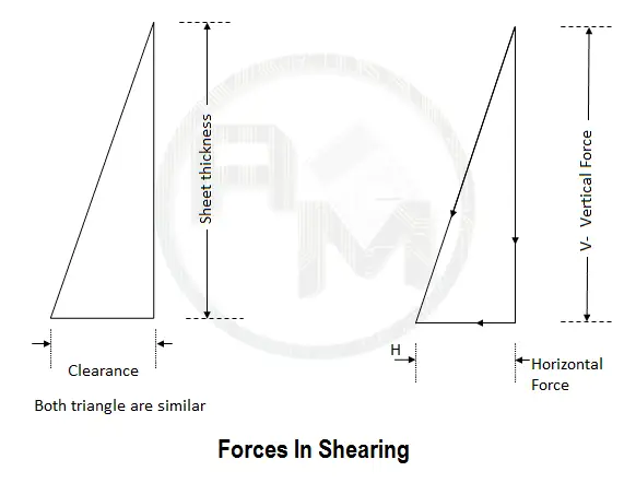
Vertical Force
The value of Vertical Component V depends upon the area to be sheared and the shear strength of the material to be cut. Shear Area is a multiple of the length of cut and sheet thickness.
Horizontal Force
The value of horizontal or lateral force H depends upon the die clearance. The horizontal force can be stated in terms of vertical force percentage. This percentage is the same as the die clearance percentage.
For perfect shearing/cutting of sheet metal, clearance must be in the proper amount.
What is Press Tool Clearance?

The amount of space between punch cutting edge and the die-cutting edge is known as clearance. For better understanding, “Clearance is the amount of extra space required in the hole of the die to allow the punch to pass through to punch a hole in the material”.
Importance of Proper press tool Clearance
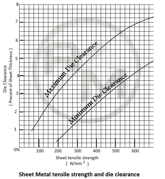
Clearance has a significant role in all cutting operations and forming operations. The die clearance depends upon the work material, it ranges from two to ten percent of the thickness of the worksheet. Ductile material should have lesser die clearance otherwise soft material would be drawn into the gap and harder material needs more die clearance for good shearing action.
Excessive clearance causes more burr on the sheared sheet while less clearance reduces the burr but it also damages the edges of the die and punch. This results in frequent resharpening of the die and the punch and decreases the press tool life.
The range of die clearances for various materials for stamping work:
Note that the die clearances are specified in the percentage of Sheet thickness. For a close cutting profile, there would be a die clearance between the die and punch all around in profile.
Die Clearance for various materials
| Material | M.S | Aluminum | Brass |
| Clearance % Sheet Thickness | 2.5% – 5% | 1.5% – 3% | 1.5% – 3% |
Note: It is not possible to get tolerances than die clearance on components so it is necessary to perform an additional shaving operation for high precision work.
Die clearance for punching press tool
The hole pierced in the sheet is a tapered one, with minimum opening equal to punch size. The maximum size of the hole at the bottom of the sheet depends upon the width of the die opening. As the minimum size is important in piercing/punching, the punch is made equal to the hole size.
The Die clearance on the die cut out is bigger than the size stated on the component drawing.
For Example
Piercing a hole of ∅ 20 mm out of 2 mm thick MS sheet.
The punch diameter will be the same as the hole size i.e 20 mm.
Die clearance at 2.5% of sheet thickness = 2.0 x 0.025
⇒ 0.05 each side
⇒ Die bore = 20 + 2 x 0.05 = ∅ 20.10 mm
Die Clearance for Blanking press tool
The blanked profile sheet is also tapered one, with minimum size at the bottom and maximum at the top. The maximum size of the hole at the bottom of the sheet depends upon the die opening. As the minimum size is important in piercing/punching, The punch is made equal to the hole size.
The maximum dimensions of the blanks should not exceed the sizes stated in components drawing. So in blanking the die cutout is made equal to the die profile hole and the punch must be lesser on every side by the clearance size.
For example:
Blanking an of ∅ 20 mm blanked sheet out of 2 mm thick MS sheet.
Die diameter will be same as hole size i.e 20 mm.
clearance at 2.5% of sheet thickness = 2.0 x 0.025
⇒ 0.05 each side
⇒ Punch Size = 20 – 2 x 0.05 = ∅ 19.90 mm
Note: What is the difference between punching and blanking tools ?
Ans: Blanking and Punching tools both are similar however the workpiece in the blanking tool called blank and used in further operation whereas in the punching tool the piece falling through the die is scrap.
Bending Press Tools Principles
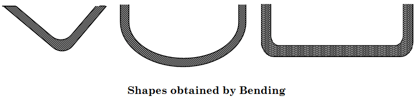
The bending process changes the shape of a flat blank to make it angular, curved, or both without much change in its thickness. It is a very common process for changing sheets and plates into channels, drums tanks, etc. During the bending operation, the outer surface of the material is in tension and the inside surface is in compression. The strain in the bent material increases with a decreasing radius of curvature.
Bend Radius
The minimum radius to which a blank can be bent without cracking depends upon the material and its hardness. The minimum inside radius also depends upon the direction of rolling. The strips should be cut in such a way that the bend lines lie at the right angle to the grain direction.
A sheet is more vulnerable to cracking in bends across the grain direction. So the minimum radius of cracking across the grain is about four times the minimum radii for bend along the grain direction. Usually, the direction of grains is parallel to the longer side of the full uncut sheet.
| Condition | Aluminum | Steel | Brass | Copper |
| Dead Soft | 0.25T | 0.5T | 0.55T | T |
| 1/4 Hard | 0.5T | T | T | 1.5T |
| 1/2 Hard | 0.8T | 2T | 1.5T | 2T |
| 3/4 hard | 1.5T | 4T | 3T | 3T |
Minimum radii for bending various materials along with the grain directions.
Where T= Thickness of material
Bend Allowance
When the metal sheet folded or bent, the metal around the bend is deformed and stretched. As this happens it gains a small amount of total length in the stamped part. The Bend Allowance is defined as the added length to the actual leg lengths of the part in order to develop a flat pattern.
The leg length is the length of the flange which is outside the bend radius.
Blank Size or Developed length
It is a necessary stamping principle to calculate the length of the blank before bending because a component is usually blanked before bending.
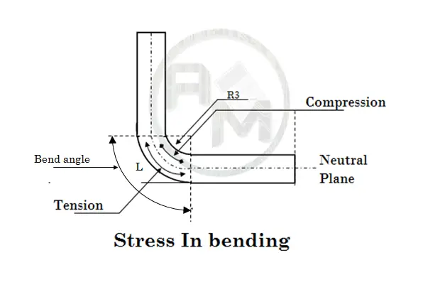
During Bending the metal layers adjacent to the inner radius are compressed while the metal layers adjacent to the outer radius are stretched. Some layers of sheet neither compress nor stretch during a bending operation called Neutral Plane.
Note: Neutral Plane lies along the middle of sheet thickness for radius more than twice thickness. For radii less than twice of sheet thickness approximately one-third thickness from the inner radius surface of the bend.
While Calculating the blank length or developed length, shifting of the neutral plane should be considered. Developed length Should be calculated along the neutral plane by following formula.
L = (π/180) A (R + 0.5T) When R >= 2T
L = (π/180) A (R + 0.33T) When R < 2T
Where,
T= Sheet Thickness
R = Inside bend radius
L= Developed Length
A = Angle of bend in degree
Example: Calculate the developed length or blank length for the following components.

Read More: What is Sheet Metal Stamping
Solution: The developed length of the component has two straight parts l1′ l2, and curved part l3.
Given:
Inner radius : 3mm
Sheet thickness : 2 mm
So
l1 = 25 – ( Sheet thickness + Inner radius ) =25 – 5 =20 mm
l3 = 45 – ( Sheet thickness + Inner radius ) =45 – 5 =40 mm
As the inside radius of the bend is less than 4 ( twice the sheet thickness )
l2 = L When R < 2T
= (π/180) A (R + 0.33T)
= (π/180) × 90 × ( 3+0.33 × 2 )
= 5.749 mm
Now Total developed Length
= l1 + l2 + l3
= 20 + 5.79 +40
= 65.79 mm
Computer-aided designing of press tools
Due to the increasing demand for press tools, a compact and practical CAD/CAM system for design of press tool can automate the following functions:
- Checking the work-piece drawing for the feasibility of manufacturing from the sheet metal stamping process press tools.
- Finding blank size for bending, forming or drawing operations.
- Selection for the types of press tools to be used.
- Calculating material utilization, pitch, margins, and angle of orientation.
- Deciding disposition of punches and shank center.
- Computing shear forces and size of the die, stripper, screws, dowels, etc.
- Selecting the press machine and Die set.
- Drafting assembly drawings and detail drawings.
Computer-aided press tool designing includes various modules like work-piece checks module, developed length blank size module, Nesting Module, Strip-Layout module, and die design module. The design check module finds out the center of pressure, tonnage required, stripping force, dimensions of punches, dies, stripper, stripper and punch plates, No. of screws, dowel pins, springs, and knock-out pins.
The designing module creates the assembly drawing with many layers for various press tools elements such as Die block, die plate, punch, punch plate, stripper, stripper plate, ejector, etc.
Nice sir very useful information about press tool .
Please send me press tool design pdf
Do you have any design piercing punch from bottom with air scution at top half? If any please share it.
please send press tool design details
Hi Raghvendra,
What design details do you want? We have some dedicated articles on press tools. You can try them once.