

Phase shift oscillator is an RC type oscillator whose output is fed back to its input through a phase shift network consisting of resistors and capacitors in a ladder network. In our last tutorials, we explain LC oscillator like Hartley, Colpitts etc, Wien bridge oscillator and crystal oscillator in detail. Here we are going to explain Phase shift oscillator and its implementations in detail.
For required positive feedback in RC oscillator, the input is shifted 180o through the amplifier stage and another 180o through the inverting stage which gets combine and gave a phase shift of either 360o or 0o because for sustained oscillations positive feedback is necessary.
RC phase shift oscillator Theory
RC phase shift oscillator is the most demandable oscillator because of its excellent frequency stability. On a wide range of loads, it can output a pure sine wave.
Phase shift circuit:
To give a desired phase shift to the signal, the RC phase shift network is used as a simple resistor-capacitor network. Depends on your requirement you can use this oscillator either as a single stage RC phase shift network or a three-stage phase shift network. As shown in the figure below, in single stage network output voltage leads the input voltage by some angle less than 90o.
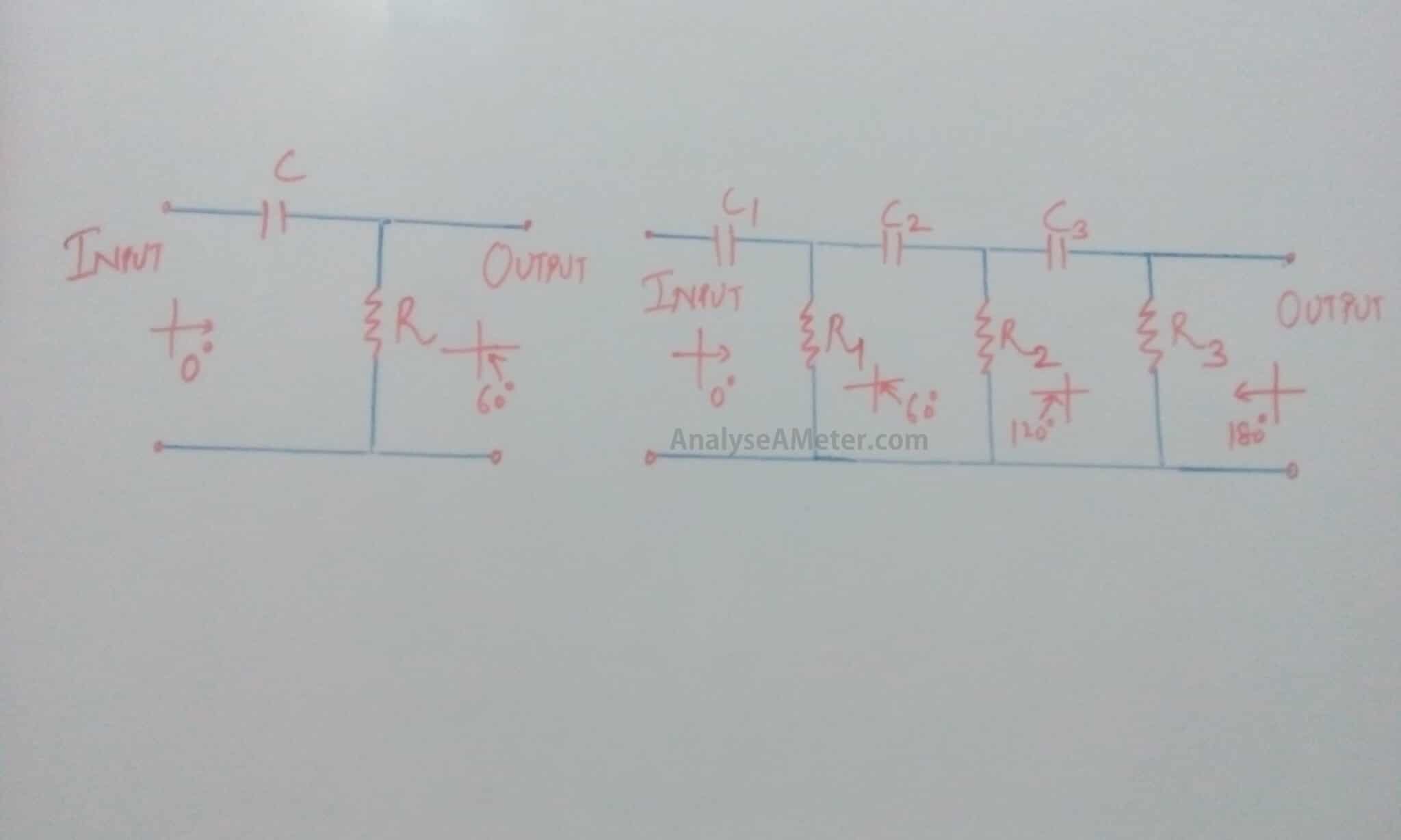
As we know for sustained oscillations, the phase shift of 180 o is necessary but by using single pole RC network we achieve phase shift less than 90 o. To overcome this problem we use three Stage RC phase shift network into which each stage gave 60 o phase shift and in total, we got 180 o at the output. Because of this reason three stage RC phase shift network is preferred as compare to single stage RC phase shift network. The circuit diagram of these phase shift networks is given above.
Phase angle:
The amount of actual phase shift in the circuit depends upon the capacitor and resistor. For required frequency of oscillation, let C be the capacitance, F be the operating frequency and R be the resistance. Then the capacitive reactance can be calculated as:
Xc = 1 / 2∏ FC … (1)
The effective impedance of the circuit can be given by the equation:
Z = √ (R2 + Xc 2)
And the phase angle of the RC network can be given as:
ɸ = tan -1 (Xc / R)
Phase shift Circuit:
We can implement phase shift oscillator circuit by using a transistor, an op amp and FET. Here we explain each its implementation in detail:
(i) RC phase shift oscillator circuit using Transistor:
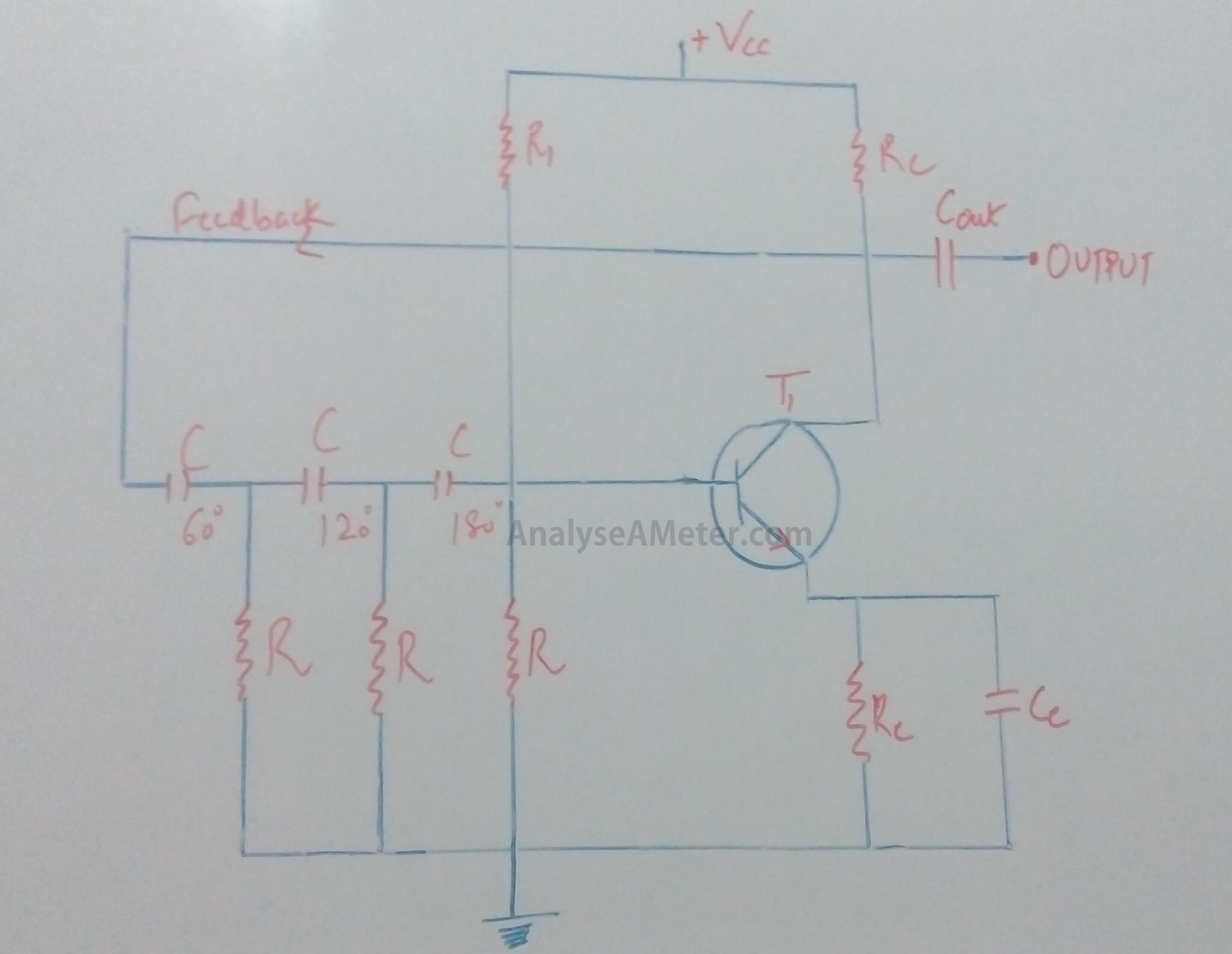
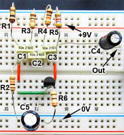
The circuit shown above is known as the basic RC oscillator which comprises of three stage RC phase shift network used to produce a sine wave at output signal through regenerative feedback. As shown in the circuit diagram, the resistor R1 and R provides a voltage divider bias to the transistor T1. Ce is the emitter bypass capacitor while Cout is the output DC decoupling capacitor, Re is used for maintaining thermal stability, Rc limits the collector current. The frequency stability of the oscillator can be maintained by using more than three stages of RC phase shift network.
By using the 3 ganged variable capacitor we maintained the resistor values same otherwise the frequency can be varied by varying one or more resistors or capacitors in the phase shift network. The frequency of RC phase shift oscillator is given as:
f = 1 / 2∏RC √2N
where f is the output frequency in hertz, R is the resistance in ohms, C is the capacitance in Farads and N is the number of RC stages.
Into this circuit, the amplifier gain must be greater than 29 to overcome the circuit losses because it produces an attenuation of -1/29th per stage. On the feedback network, the loading effect of the amplifier has an effect on the frequency of oscillations and can cause the oscillator frequency to be up to 25% higher than calculated.
(ii) RC phase shift oscillator using FET:
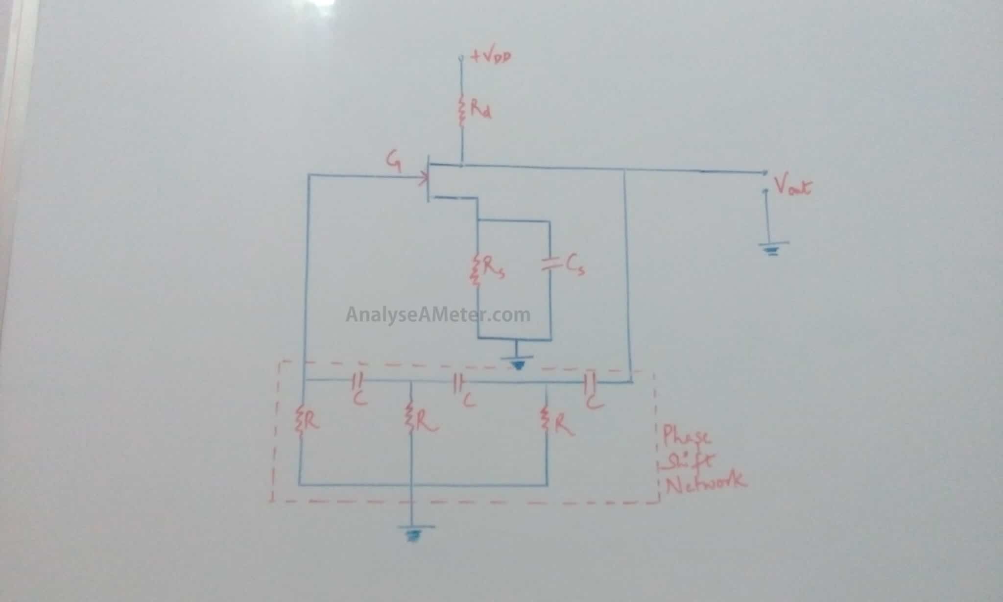
The circuit is shown above consists of a common source FET amplifier followed by a three stage RC phase shift network. With a capacitor bypassed source resistor Rs and a drain resistance Rd, the amplifier stage is self-biased. The Phase shift of 180o between the amplified output voltage Vout and the input voltage Vin at the gate is produced by the amplifier itself if the loading effect of the phase shift network on the amplifier can be assumed to be negligible. To maintain the positive feedback, the three stage RC phase shift network produces an additional phase shift equal to 180o at some frequency of operation. This frequency will be the one at which the circuit will oscillate and provide the large magnitude of the amplification. In this oscillator we use voltage series feedback i.e. feedback voltage is proportional to the output voltage Vout.
As we know, the frequency of oscillator depends upon the values of capacitors and resistors used in the phase shift network. Using basic RC circuit analysis technique, RC phase shift oscillator Frequency derivation can be derived as follows:
Xc = √ 6R… (2)
Compare equation (1) and (2);
√ 6R = 1 / 2∏ FC
F = 1 / 2∏ RC √ 6
If variable capacitors are used then the frequency can be adjusted over a wide range.
(iii) RC phase shift oscillator using Op-amp:
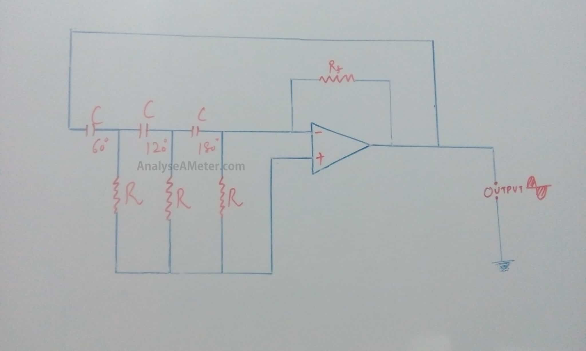
The circuit shown above indicates that the feedback is connected to the inverting input of the operational amplifier which produces the required 180ophase shift. Another 180o phase shift is produced through the three stage RC phase shift network which got combine with feedback phase shift and produces 360o or 0o phase shift which is the required condition for sustained oscillations. RC oscillators with four stages are generally used because available op-amp came in quad IC packages.
Phase shift oscillator advantages:
Due to its extraordinary features, it is the most demandable oscillator. Following of its advantages are:
- It provides good frequency stability.
- It is not bulky and expensive.
- It is suitable for low frequencies to say as of the order of 1 KHz.
- It generates a sinusoidal output which is distortion free.
- It is simpler than Wien bridge oscillator because it does not need negative feedback and stabilization arrangements.
Hope you all like this article. For any suggestions please comment below. We always appreciate your suggestions.