

A Full wave rectifier is a kind of rectifier that rectifies both waves (positive and negative) of the input signal, unlike a half-wave rectifier circuit. In this way, this uses the full signal and the wastage is minimum. And so the efficiency is maximum. The full-wave rectifier circuit is also of 2 types i.e. Center Tapped and Bridge Rectifier. Unlike the Half wave rectifier, this rectifier circuit is mostly used because of its high efficiency.
We have already discussed the rectifier circuits and half-wave rectifier circuit in detail in our previous tutorials. From those tutorials, we got to know that there is a vast difference in the characteristics and efficiency of different rectifiers.
Now in this tutorial, we will learn about the types, characteristics, and properties of a full-wave rectifier in detail.
What is the Full Wave Rectifier?
A Full wave rectifier is defined as “a type of rectifier that converts the alternating voltage into pulsating direct voltage using two crystal diodes that conduct current alternatively. But unlike half wave rectifier, it uses both cycles of the input voltage. For this AC to DC conversion process (rectification), it uses 2 diodes.“
This rectifier acts as a heart of circuitry which allows the sensors to attach to the RCX in either polarity.

In this rectifier, the full-wave rectification process is achieved by using two crystal diodes. During the positive as well as the negative half cycle of input AC, the two circuits are employed to obtain the same direction of current flow in the load resistor.
Full Wave Rectifier Circuit: Working & Operation
As we have mentioned in starting, this rectifier is further classified into 2 types namely: Center Tap Full-wave Rectifier and Full-wave Bridge Rectifier. Each of these has its own working operation and features. We have covered these two rectifiers in detail below with working and properties. Focus on circuit diagrams and waveforms for a better understanding of each rectifier.
To better understand the circuit, we recommend going through our detailed article on PN Junction Diode
Center Tap Full-wave Rectifier Circuit
A Center Tapped Full-wave Rectifier Circuit employs a tapped transformer with secondary winding AB tapped at the center point C, and two diodes D1 and D2 connected in the upper half and the lower half portion of the circuit.
For rectification of a signal wave, the Diode D1 utilizes the AC voltage appearing across the upper half of the secondary winding, while Diode D2 uses the lower half of the secondary winding.
This rectifier is widely used in the vacuum tubes and thermionic valves.
Center Tapped Rectifier Working Operation
The circuit diagram of the center tap full-wave rectifier circuit with waveform is shown in the below figure. If you follow the direction of the arrows in the circuit closely, you will notice that the alternating voltage Vin appears across the terminals AB of the secondary winding of the transformer when the AC supply is switched on.
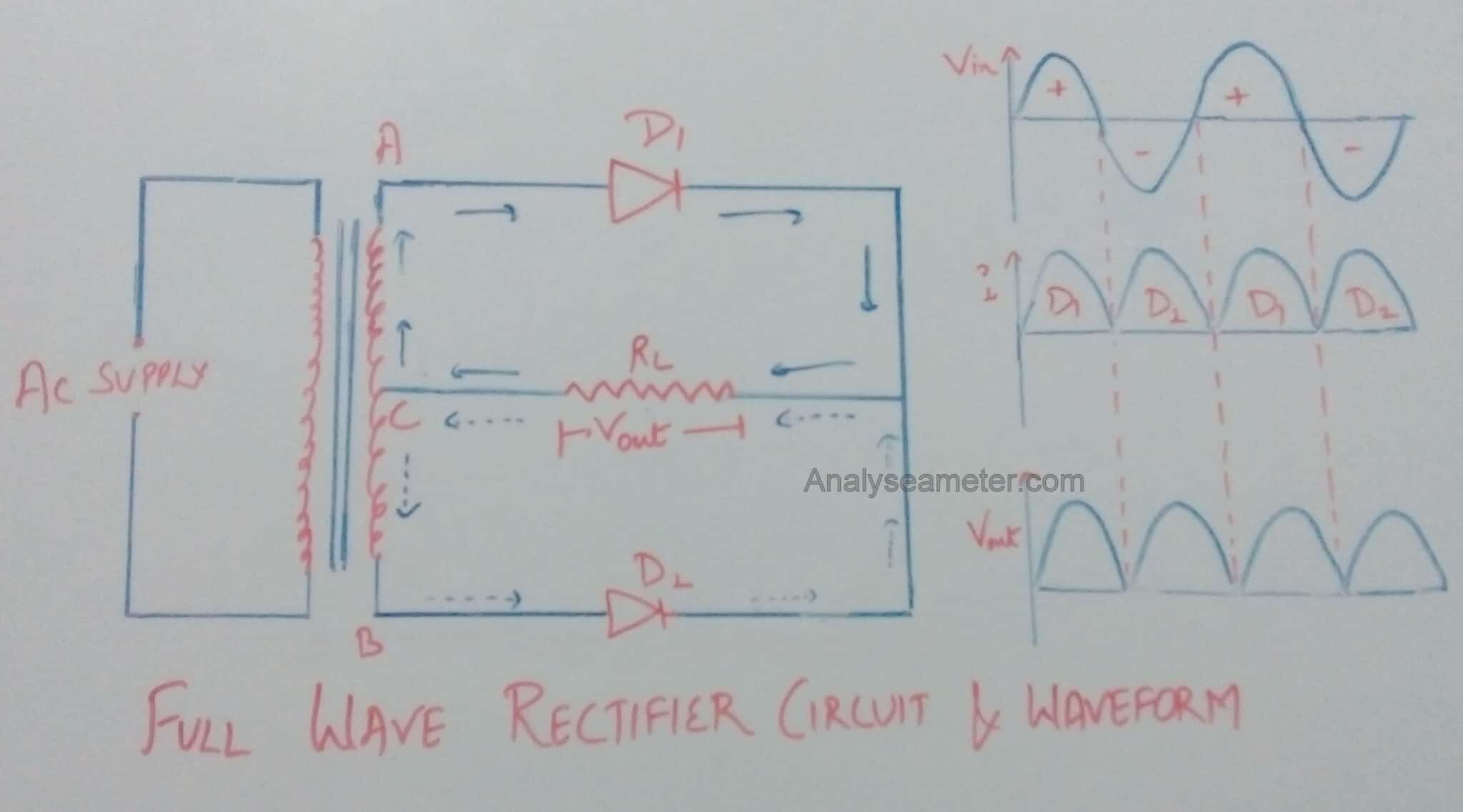
Positive Half Cycle Rectification:
During the positive half cycle at a given voltage, end A of the transformer becomes positive while end B becomes negative. This makes the D1 diode forward biased and the D2 diode reverse biased. Due to this reason, only the diode D1 conducts current while D2 does not conduct current.
As shown in the above figure, the current starts flowing through diode D1, and output voltage Vout is measured across load resistor RL. This means current flows only in the upper portion of the secondary winding of the transformer. The path of the current is shown by bold arrows.
Negative Half Cycle Rectification:
During the Negative Half Cycle in the center-tapped rectifier, the end B of the transformer becomes positive while the end A becomes negative. This makes the D1 diode reverse biased and the D2 diode forward biased. Due to this reason, now the diode D1 does not conduct current while D2 conducts.
As shown in the figure above, the current starts flowing through diode D2, and through load resistor RL in the lower portion of the secondary by dotted arrows.
Note: During Negative as well as positive half-cycle of the input AC voltage, the current flows through the load resistor RL in the same direction.
Therefore across the load resistor RL, DC output voltage Vout is obtained.
The waveform diagrams of the current flowing through the load, applied input voltage, and output voltage developed across the load are shown in the above figure.
Full-wave Bridge Rectifier Circuit
A Bridge Rectifier is another type of full-wave rectifier that uses 4 diodes instead of 2. It also does not require any center tapping. As the name suggests, it is a bridge rectifier, so we can already conclude with its name that it uses a bridge circuit.
These 4 individual rectifying diodes are connected in a closed-loop bridge configuration. Another interesting fact about the full-wave bridge rectifier is that it is smaller in size & cheaper in cost. This is because it has no requirement for a special center-tapped transformer makes.
Full-Wave Bridge Rectifier Working Operation

As shown in the figure above, the bridge rectifier has 4 diodes; namely D1, D2, D3, D4. Out of these 4 diodes of the bridge, only two diodes conduct at a time. Either “D1 and D3” conduct or “D2 and D4” conduct or vice-versa depending upon the positive or negative half cycle fed to the bridge circuit.
Now, let us understand this taking both cases:
Positive Half Cycle Rectification:
When the positive half cycle is fed to the bridge circuit, Diodes D2 (because of positive voltage) and D4 (because of negative voltage) are positively biased. While Diode “D1 and D3” are negatively biased. This means only “D2 and D4” will conduct.
The direction of the current is shown in the above figure.
Negative Half Cycle Rectification:
When the negative half cycle is fed to the bridge circuit, Diodes “D1 and D3” are positively biased. While Diode “D2 and D4” are negatively biased. This means only “D1 and D3” will conduct.
The direction of the current is shown in the above figure.
Here most important point to note is, the direction of the current flow is the same in both cases. This means, the current is unidirectional and so the voltage-drop is also unidirectional.
You can also watch the video on the Full-Wave Rectifier by Neso Academy for better understanding.
Full-wave Rectifier Characteristics Analysis Equations
For the analysis of Full wave rectifier following parameters or properties are considered. The different characteristics are explained with derivation equations below in detail.
1. Ripple Factor Calculation
Ripple factor is defined as the ratio of the RMS value of the AC component to the DC component. Therefore,
Ripple factor = RMS value of AC component / value of DC component
This factor mainly decides the effectiveness of a rectifier i.e. smaller the value of this factor, the lesser is the AC component in comparison to the DC component. Hence, more effective is the rectifier.
The Ripple Factor of Full wave rectifier can be calculated as follows:
As we know,
Irms = √ Idc2 + Iac2
Where,
Irms = RMS value of total load current
Idc = value of dc component of the load current
Iac = RMS value of the AC component of load current
Therefore,
Iac = √ Irms2 – Idc2
As we know,
Ripple factor = Iac / Idc
= √ Irms2 – Idc2 / Idc
= √ (Irms / Idc)2 -1
So, the ripple factor of a full-wave rectifier is calculated as:
As we know,
Irms / Idc = ( Im / √ 2) / (2 Im /π) = 1.11
Therefore,
Ripple factor = √ (1.11)2 -1 = 0.482
2. Full-Wave Rectifier Efficiency Calculation
The efficiency of the rectifier is defined as the ratio of DC power output to the input AC power. Therefore,
Efficiency = DC power output / AC power input
= 0.812 RL / (rf + RL)
If rf is neglected as compared to RL, the efficiency of the rectifier is the maximum and is given as;
ηmax = 0.812 = 81.2%
Hence the efficiency of the full-wave rectifier is 81.2%. Or we can say that the Full-wave rectifier is 81.2% efficient.
3. Peak Inverse Voltage (PIV)
Peak inverse voltage is defined as the maximum value of the voltage coming out of the diode when it is reverse biased during the negative half cycle. For the center tap full wave rectifier, its value is 2Vm and for the bridge rectifier, its value is Vm.
Transformer Utilization Factor (TUF):
It is defined as the ratio of power delivered to load and VA rating of the transformer. For the center tap full wave rectifier, its value is 0.573 and for the bridge rectifier, its value is 0.812.
Advantages and Disadvantages
Advantages:
Advantages of the full-wave rectifier are:
- The output and efficiency of center tap full wave rectifier are high because the AC supply delivers power during both the halves.
- For the same secondary voltage bridge rectifier has double output.
Disadvantages:
The disadvantages of full-wave rectifier are as following:
- A full-wave rectifier requires more diodes i.e two for the center tap rectifier and four for the bridge rectifier.
- When a small voltage is required to be rectified the full-wave rectifier circuit is not suitable.
- In center tap full wave rectifier, center on the secondary winding for tapping is difficult.
Hope you all like this article. For any suggestions please comment below. We always appreciate your suggestions.
Nice one
Use more simple word.
This writing is very nice.
Thank you.
I got all the explanation and Description which I wanted.
Thank you very much
Thanks Munna,
We are glad to know you liked our work. And also we appreciate you took your time to comment.
Very useful thank you
Great benefits….. I want to know the reference book, actually, I would like to make a seminar from this.
grateful for the lesson keep it up and continue researching on more
Hi Brian,
Thanks for commenting. It keeps us motivated. In the coming weeks, we are going to share some projects based on different festival presents and decoration. Make sure to read them and drop your valuable comments.
vry useful article…i like it too much
Thanks Prachi,
We are glad that it is helpful to you. Like our page on fb and share with your friends. And if you have any doubt about the topic, ask in the comment section. 🙂
thank you very much because of this leasson
Thanks for reading. Our pleasure. Keep visiting our site for more information.