Crystal oscillator is an electronic oscillator used to create an electrical signal of precise frequency by using the vibrating crystal mechanical resonance made of piezoelectric material. In our previous articles, we explain Hartley oscillators and Colpitts oscillators in brief. Here we are going to explain crystal oscillator and its circuit diagram in brief.
There are different types of piezoelectric resonators available in the market but because of a high degree of stability quartz crystal is mostly used. Quartz crystal basically operates up to frequencies ranging from a few tens of Kilohertz to hundreds of megahertz. It is used in many devices such as clocks, radios, computers, cell phones and also found in measurement equipment such as counters, oscilloscopes, and signal generators.
Crystal oscillator circuit
For sustaining oscillations in crystal oscillator circuit, we firstly take voltage signals from quartz resonator, amplifying them and feeding them back to the resonator. When a voltage is applied across the faces of the crystal, then it starts changing its appearance or shape, producing a characteristic known as the piezoelectric effect. Due to this effect, the shape of the crystal changes indicates that the electrical charge is directly proportional to the mechanical force i.e. by changing the shape of the crystal electrical charge produces a mechanical force and vice versa, a mechanical force applied to the crystal produces an electrical charge.
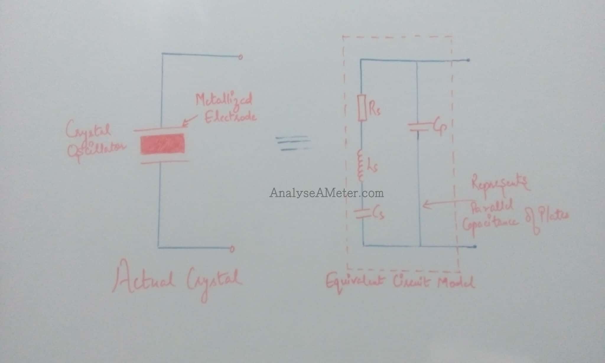
The above figure shows the electronic symbol for a piezoelectric crystal resonator which consists of two metalized electrodes and quartz crystal. In its equivalent electrical circuit, series RLC circuit i.e. represents the mechanical vibrations of the crystal is connected in parallel to the capacitance i.e. represents the electrical connections to the crystal. The frequency at which the equivalent impedance of the crystal has a series resonance where Cs resonates with inductance Ls is known as crystal series frequency. When Ls and Cs resonate with the parallel capacitor Cp then second frequency also established as well as series frequency. The formula of the series resonant frequency and parallel frequency is given below:
Fs = 1 / 2∏ √ Ls Cs
Where
Fs = Series Resonant frequency
Fp = 1 / 2∏ √ Ls Cs (Cp Cs / Cp + Cs)
Where
Fp = Parallel resonant frequency
Crystal oscillator design
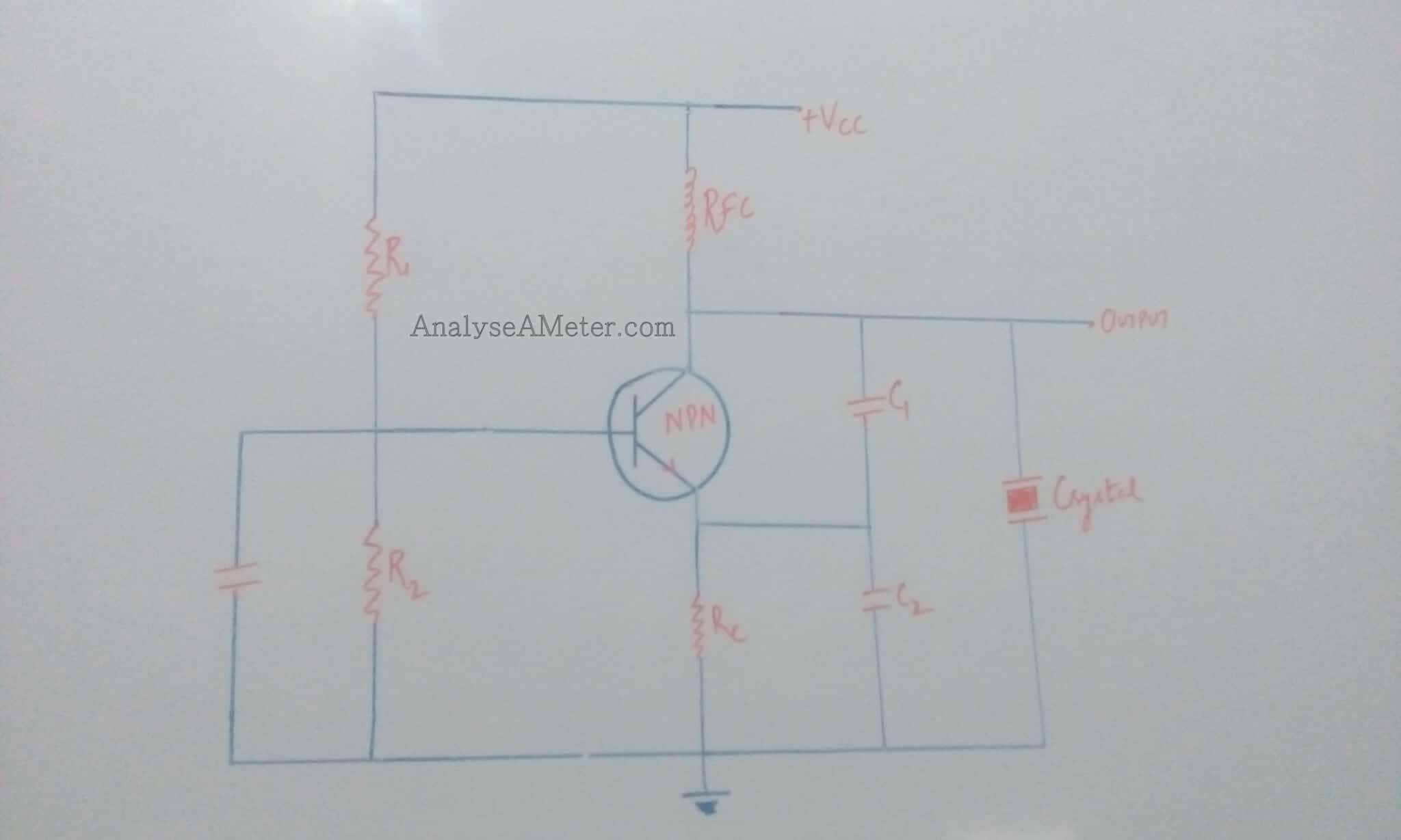
To stabilize the frequency of oscillation, a crystal may be operated at either its series or parallel resonant frequency.
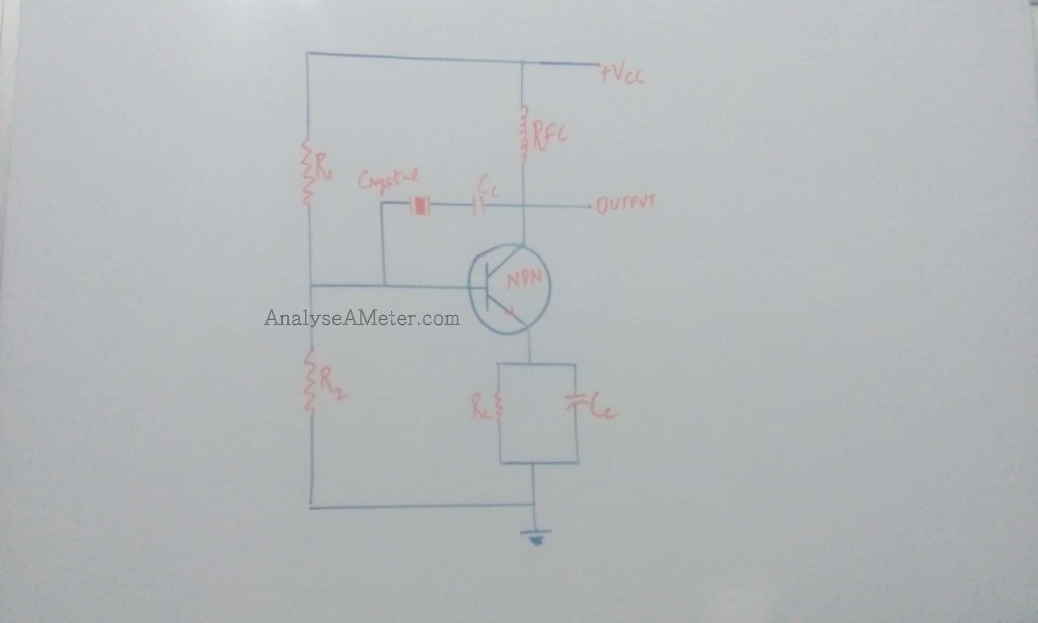
As shown in the figure above, we connect a crystal as a series element in the feedback path for operation in the series resonant mode. In this mode of operation, the crystal impedance is the smallest and the amount of positive feedback is the largest. Resistors i.e. R1, R2, Re connected provide a voltage divider stabilized dc bias circuit, RFC (radio frequency coil) provides dc bias while decoupling any ac signal on the power lines and capacitor i.e. Ce connected provides AC bypass of the emitter resistor (Re). Coupling capacitor i.e. Cc connected blocks dc between collector & base and has a negligible impedance at the circuit operating frequency. When the crystal impedance is minimum then the voltage feedback signal from the collector to the base is maximum. This type of circuit is known as Pierce crystal. As a result, the circuit frequency of oscillations is set by the series resonant frequency of the crystal which is not affected by any variations in the transistor parameter and supply voltage.
As per specifications listed by the manufacturer, crystal oscillators must be designed to provide a load capacitance on the crystal. The maximum power for plated crystal varies from 2mW to 10mW. If the maximum power is supplied to the crystal, it causes overheating of the crystal & renders the resonant frequency unstable because too much power leads to distortion in the oscillator waveform. The maximum drive power limits the AC voltages applied to the crystal. The maximum AC voltage may be determined by using equation P= V2 / R where R is the resistance and V are the voltage of the individual crystal.
Applications of Crystal Oscillator:
Crystal oscillators are used in many applications in different areas. Following of the applications are:
- In Research and development, it is used for space tracking purpose, measuring instruments & medical devices, space tracking purpose etc.
- In Automotive, it is used for stereo, clock & to trip computer, GPS system and engine controlling.
- In Military and Aerospace, it is used for electronic warfare, guidance system, navigation purposes and establishes efficient communication system.
- It is used in many consumer goods such as video cameras, toys & video games, cellular phones, Cable television systems, personnel computers, radio systems etc.
- In industries, it is used in phase locked loop system, modems, sensors, digital systems, telecommunications, disk drive, instrumentation etc.
Hope you all like this article. For any suggestions please comment below. We always appreciate your suggestions.
One Comment