
More topics on Transistors:
Transistor basics Transistor operation Transistor characteristics Transistor configurations Transistor as a switch common emitter amplifier Darlington transistor
Oscillator is an electronic circuit that produces a periodic, oscillating signal often a square wave and a sine wave. It basically converts direct current from a power supply to an alternating current signal. In our previous articles, we explain how we can use a transistor as an amplifier and its configurations. Here we are going to put some shadow on how we use a transistor as an oscillator, its mechanisms and types.
Transistor as Oscillator
When we use a transistor in a circuit, it continuously produces undamped oscillations at the output terminals of the circuit. Here we can explain you how to use a transistor as an oscillator with the help of circuit diagram.
Oscillator circuit:
The diagram of Transistor oscillator circuit is shown below. This circuit is divided into three sections:
(i) Tank Circuit: This circuit produces oscillations which are amplified by the transistor and produces amplified output in the collector side.
(ii) Amplifier circuit: This circuit basically amplifying the small sinusoidal oscillations present in the base-emitter circuit and generates output in the amplified form.
(iii) Feedback circuit: This is the important section of the circuit because to amplify the oscillations for the amplifier we need some energy at the tank circuit. For this purpose, we fed back the energy of the collector circuit to the base circuit through the phenomenon of Mutual induction. We fed back the energy from output to input with the help of this circuit.
As we know, in this situation we can say that when flux in one coil increases then the flux in the other coil opposes means phase variation takes place when it is fed to the other side. In common emitter amplifier when we look out at the output voltage, the output is always in the opposite phase with respect to the input indicates that the one phase variation takes place from the input to the other side and other takes place from output to the input side via feedback circuit. Therefore, the feedback oscillations in this situation will be exactly in the same phase as that of the nature of oscillations.
Mechanism/ Working of Transistor Oscillator circuit:
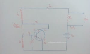
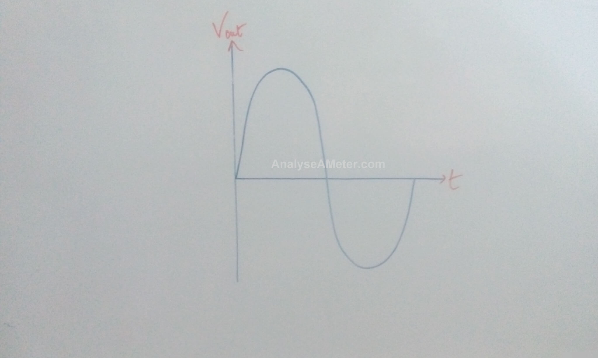
In oscillator circuit design, transistor is being used as a common emitter circuit into which emitter is common with the base as well as collector terminals. Between the input terminals i.e. between emitter and base, we have connected a tank circuit. The tank circuit is an electric circuit into which inductor (L) and capacitor (C) are connected in parallel which produces oscillations in the circuit. Due to the oscillations of voltage and charge in the tank circuit, the base current fluctuates and because of this fluctuation, the forward biasing of the base current varies periodically. As a result, the collector current also starts varying periodically. More precisely as we say that the LC oscillations are sinusoidal in nature and due to this both the collector current and base current are varying sinusoidally. As shown in the figure, if the collector current is varying sinusoidally then the output voltage obtained can be written as Ic RL can be considered as a sinusoidal output. When we draw a graph between output voltage Vout and time then the curve obtains is sinusoidal in nature. Now for continuous oscillations in the tank circuit we need some energy but in this circuit no battery or dc source is available. For this purpose, we connect mutually inductor L2 and L1 present in the collector circuit and base circuit through a soft iron rod. This soft iron rod will link the inductor L2 to inductor L1 and due to its mutual induction, a part of the energy in the collector circuit will be linked to the base side of the circuit. As a result, the oscillation in the tank circuit is continuously sustained and amplified.
Conditions for oscillation:
For sustained oscillation, an oscillator circuits must meet the following conditions:
- The loop phase shift must be 0 ͦ and 360 ͦ .
- The loop gain must be slightly greater than unity.
- The voltage gain around the closed feedback loop Acl is the product of the amplifier gain Av and the attenuation B of the feedback circuit.
Acl = AvB
- If a sinusoidal wave is the desired output, a loop gain greater than 1 will rapidly cause the output to saturate at both peaks of the waveform and producing unacceptable distortion.
- If the amplifier gain is greater than 100, it will cause the oscillator to limit both peaks of the waveform.

To meet these conditions, the oscillator circuit must include some form of amplifier and a portion of its output must be fed back regeneratively to the input. In other words, feedback voltage must be positive so it is in phase with the original excitation voltage at the input. To overcome the losses in the input circuit, i.e. gain equal to or greater than unity we use the feedback circuit. If the gain of the amplifier is less than unity, the circuit will not oscillate while if it is significantly greater than unity, the circuit will be overdriven and produce distorted waveforms (non- sinusoidal waveforms).
Types of oscillators:
Oscillators are the most demandable component of the electronic industry. We generally divided it into two categories:
(i) Feedback oscillators:
- Feedback oscillators are those oscillators which basically return a fraction of the output signal to the input with no net phase shift, resulting in an augmentation of the output signal.
- It consists of an amplifier for gain (either an op-amp or discrete transistor) and a positive feedback circuit that produces phase shift and provides attenuation.
- When oscillations start, the loop gain is fixed at 1.0 to maintain sustain oscillations.
(ii) Relaxation oscillator:
- Relaxation oscillator uses an RC timing circuit to generate a waveform that is generally a square wave or other non-sinusoidal waveform.
- This oscillator uses a Schmitt trigger or other device that changes states the state of the capacitor from charging to discharging through a resistor.
Hope you all like this article. For any suggestions please comment below. We always appreciate your suggestions.
This post cleared all my doubt related to this topic. So, thank you so much for uploading this post.