

A Digital Multimeter can measure variety of electrical functions such as Current, Voltage, Resistance etc.
We encounter digital multimeter or DMM in electronics or electrical study every then and now. You might have used or saw an electrician using it to find fault in a connection.
Here I am going with easy step by step explanation with diagrams to make you understand its working and different features.
What is a Digital Multimeter
A digital multimeter or DMM is a test equipment used for resistance, voltage, current measurement, and other electrical parameters as per requirement and displaying the results in the mathematical digits form on an LCD or LED readout. It is a type of multimeter which functions digitally rather giving an analog output.
Digital multimeters are widely accepted worldwide as they have better accuracy levels and ranging from simple 3 ½ to 4 ½ digit handheld DMM to very special system DMM.

Features of Digital Multimeter
The Digital multimeter is the most advanced measuring instrument that makes use of modern Integrated circuits for making electrical measurements. Some of its features which make it famous in the eyes of professional technicians are:
- It is light in weight.
- Capable of giving more accurate readings.
- It measures lots of physical quantities like voltage, current, resistance, frequency, etc.
- It is less costly.
- It measures different electrical parameters at high frequencies with the help of special probes.
Block diagram of Digital multimeter
The Key process that occurs within a Digital multimeter for any measurement that takes place is that of voltage measurement. If you measure voltage then you can easily measure other electrical parameters with the help of mathematical formulas.
To understand how digital multimeter works, first of all, we have to understand this process.
As we know, Digital multimeters gave output in numeric form due to ADC registers present inside these multimeters. One that is most widely used in digital multimeters, DMMs is known as the successive approximation register or SAR. For better accuracy, these SAR ADCs may have resolution levels of 12 bits.
Generally, a Digital multimeter has resolution levels of 16 bits with speeds of 100k samples per second. These levels of speed are more than adequate for most DMM applications, that’s why we are using these registers depending upon the requirement.
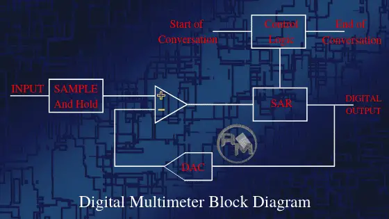
As shown in the diagram, the first stage of the process is a sample and hold used to sample the voltage at the input of the Digital multimeter and then to hold it steady. The output of the first stage becomes one of the inputs of the operational amplifier and another input of the op-amp is digital output feedback through the DAC.
The output obtained becomes the input of the SAR which generates results in digital form with a good resolution level. With a steady input voltage, the resister starts at half its full-scale value. It basically sets the most significant bit, MSB to “1” and all the remaining ones to “0”.
To see how it works take the simple example of a 4-bit SAR. Its output will start at 1000. If the voltage is less than half the maximum capability the comparator output will be low and that will force the register to a level of 0100. If the voltage is above this, the register will move to 0110, and so on.
Operation of Digital multimeter
The flow chart given below shows the operation flow of the digital multimeter.
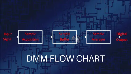
As shown above, sample acquisition is done with the help of the sample and hold circuit. Inside the sample and hold circuit the capacitor is present which gets charge to match the input analog voltage known as the acquisition process.
When the capacitor is released from the acquisition circuit then the voltage is considered to be sampled. After this, the noise generally comes which will adversely affect the accuracy of the digital multimeter. To overcome this, we buffered and averaged the samples to achieve high accuracy and resolution.
After knowing this you can easily use a Digital multimeter for measurements of electrical parameters like Ac & Dc voltage, current, Resistance, capacitance etc.
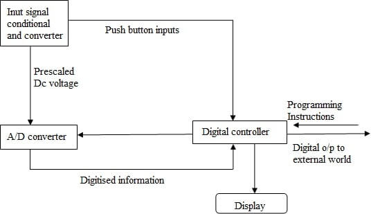
Working Principle of Digital Multimeter
As shown in the block diagram, in a typical Digital multimeter the input signal i.e. ac or dc voltage, current, resistance, temperature, or any other parameter is converted to dc voltage within the range of the ADC. The analog to digital converter then converts the pre-scaled dc voltage into its equivalent digital numbers which will be displayed on the display unit.
Sometimes, a digital controller block is implemented with a microcontroller or a microprocessor to manage the flow of information within the instrument. This block will coordinate all the internal functions as well as transferring information to external devices such as printers or a personal computer.
In the case of some handheld multimeter, some or all of these blocks may be implemented in a VLSI circuit while the A/D converter and display driver can be in the same IC.
Digital Multimeter as Voltmeter, Ammeter and Digital Ohmmeter
In digital multimeter, we can incorporate many types of meters like ohmmeter, ammeter, a voltmeter for the measurement of electrical parameters. Its block diagram is shown below in the figure. Let us have a look at its working and specification one by one.
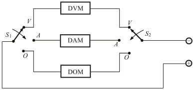
(i) Digital voltmeter (DVM):
Digital voltmeter is the basic instrument used for measurement of voltage through the use of Analog to Digital converter. The basic principle behind digital multimeters is the Analog to digital converter because without this we are not able to convert the analog output into digital form.
There are several ADC available in the market, but we mainly use Flash type ADC due to its simplicity and fastest speed. Let’s have a look at its basic operation.
(a) Flash AD converter: It comprises comparators, encoders, and digital displays. Comparators are driven by a resistor divider network, the encoder converts its inputs to corresponding outputs that drive the digital display.
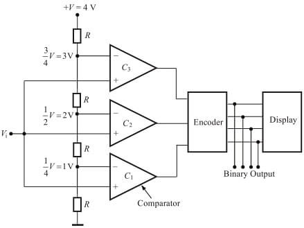
As shown above, three resistors of value R drives the comparators C1, C2, C3. Let the input voltage Vi = 1V, +V= 4V and comparators i.e. C1 , C2, C3 voltages equal to 1V, 2V and 3V respectively. If the output of the C1 = +1 and C2=C3= 0, then we fed 001 as the input to the encoder which further converts it into 0001.
This binary output drives the seven segment display to read 1V on it. With the help of this method, we read the voltages of magnitude 1V, 2V, 3V and we also add more comparators for more accurate readings as per our requirement.
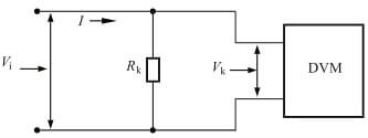
(ii) Digital Ammeter (DAM):
A digital ammeter uses a shunt resistor to produce a calibrated voltage proportional to the current flowing. As shown in the diagram, to read the current we must first convert the current to be measured into a voltage by using a known resistance RK. The voltage so developed is calibrated to read the input current.
(iii) Digital ohm meter (DOM):
A digital ohmmeter is used to measure electrical resistance which obstructs the path to the flow of current.
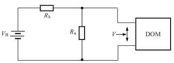
As shown in the diagram, a resistance network comprising of a known resistance RK and unknown resistance Ru used to develop a voltage across the unknown resistance. The voltage is given by:
V = VB Ru / RK + Ru
where VB = Voltage of the built-in battery
After calibrating voltage, the meter can be calibrated in terms of ohms.
What do symbols on Digital Multimeter mean?
Some common Digital multimeter symbols and its description are given in the table below. These symbols are often found on the multimeter & their schematics are designed to symbolize components and reference values of electrical parameters.
[su_table responsive=”yes”]
| Symbol | Measurement Function | Description |
| ~ | AC voltage | Measures Ac voltage value in the circuit |
| DC voltage | Measures Dc voltage value in the circuit | |
| Hz | Hertz | Measures Frequency |
| Ω | Ohm | Measures resistance value in the circuit |
| Diode | A Device used to control the direction of flow of current | |
| µF | MicroFarad | Unit of capacitor |
| Capacitor | A Device used to store electrical charge | |
| Continuity | Audible indication of continuity for low resistance | |
| A | Ampere | Measures Value of Current in circuit |
| CE | European Union Directive | It indicates the guarantee of an instrument |
| Caution | Refers to the instruction before use and indicates that its misuse results in equipment failure | |
| REL | REL | Measures relative or offset reading |
| Min/Max | Minimum and Maximum | Shows minimum and maximum recorded readings |
[/su_table]
DMM Parts and functions
A Digital Multimeter is divided into three parts:
(i) Display: The LCD screen present on the upper portion of the multimeter basically displays four or more digits and also shows a negative value if necessary. A few of today’s multimeters have illuminated the display for better viewing in low light situations.
(ii) Selection Dial: It allows the user to set the multimeter to read different electrical parameters such as milliamps (mA) of current, voltage, resistance, capacitance, etc. You can easily turn the dial anywhere for specific parameter measurements.
(iii) Ports: Two ports are available on the front of every multimeter except in some four ports are available for measuring current in mA or A. We plugged two probes into these ports which are of different colors i.e. one is of red color and the other is of black color. Different Ports in multimeter are:
(a) COM: It stands for common and is almost connected to the ground or considered as a -ve connection of a circuit. We generally insert the black color probe into the COM port.
(b) mAVΩ: This port allows the measurement of current (up to 200 mA), voltage and resistance; and is considered as a +ve connection of a circuit. We generally insert the red color probe into the mAVΩ port.
DMM Leads:
In the box of a digital multimeter, we got leads of different colors. Here we are going to explain these leads in detail. DMM leads are subdivided into four parts:
(i) Red lead
- Connected to voltage, resistance, or ampere port.
- Considered as a +ve connection of a circuit
(ii) Black lead
- Connected to the common or ground port
- Considered as a -ve connection of a circuit
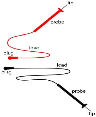
(iii) Probes:
These are the handles used to hold the tip on the tested connection. There are different types of probes available, they are:
- Banana to Alligator Clips: These are great cables for connecting to large wires or pins on a breadboard. Good for performing longer-term tests where you don’t have to hold the probes in place while you manipulate a circuit.
- Banana to IC Hook: IC hooks work well on smaller ICs and legs of ICs.
- Banana to Tweezers: Tweezers are handy if you need to test SMD components.
- Banana to Test Probes: If you ever break a probe, they are cheap to replace.
(iv) Tip:
These are present at the end of the probes and basically, provide a connection point.
Digital Multimeter Measurement Time:
Professional technicians always prefer those instruments whose time of measurement plays a crucial role leads to good results with better accuracy. Measurement of time basically depends on the following factors:
i) Settling time: When the value to be measured is applied to the input of the circuit it would take a certain time to settle is known as settling time. This will overcome any input capacitance levels when high impedance tests are made.
(ii) ADC calibration time: In some DMMs, a calibration is periodically performed must be accounted for especially where measurements are taken under automatic or computer control.
(iii) Switch time: The switch time is the time required for the instrument to settle after the input has been switched. This includes the time to settle after a measurement type has been changed, e.g. from voltage to resistance, etc.
(iv) Auto-zero time: To ensure accuracy it is necessary to zero the meter when auto-range is selected, or range changes are made.
(v) Signal measurement time: This is the basic time required to make the measurement itself. For AC measurements, the frequency of operation must be taken into account because the minimum signal measurement time is based on the minimum frequency required of the measurement.
Digital Multimeter Accuracy
A Digital multimeter is an ideal choice for every professional technician because of its better accuracy. It is the amount by which the displayed reading can differ from the actual input. Digital multimeter usually defines accuracy as a percentage of reading plus a percentage of full-scale value. Accuracy depends upon the specifications of the instrument varies from manufacturer to manufacturer. There are a number of ways in which the multimeter accuracy may be expressed:
- DMM Accuracy = ±(ppm of reading + ppm of range)
- DMM Accuracy = (% Reading) + (% Range)
- DMM Accuracy = (% Reading) + Offset
Note: Here ppm refers to parts per million.
Factors affecting the accuracy of Multimeter are:
(i) Temperature: To a large extent, the temperature can affect the accuracy of Digital multimeters. Today many multimeters have an inbuilt temperature feature which eliminates the need for any external device. You can express them as ±(ppm of reading + ppm of range)/°C.
(ii) Resolution: Resolution is directly proportional to accuracy. If you want accuracy you have to take care of resolution also. The resolution of a Digital multimeter is expressed in terms of the number of digits displayed. Typically this will be a number consisting of an integer and a half i.e.3 ½ digits etc. By convention, a half digit can display either a zero or 1.
Note: Different multimeters from different manufacturers may work in different ways. It is always recommended to consult the manufacturer’s instructions to understand how a particular digital multimeter works.
DMM Safety Precaution:
Before operating multimeters, we have to follow some safety precautions. Here we are going to explain to you some safety information about DMM.
- If the DMM test leads are damaged then never use the meter.
- Always ensures that the test leads and dial are in the right position for the desired measurement.
- When a test lead is plugged into the 10 A or 300mA input jack then never touch the probes to a voltage source.
- When power is applied never measure resistance in a circuit.
- While making measurements always keep your fingers behind the finger guards on the test probes.
- To avoid damage or injury, never use the meter on circuits that exceed 4800 watts.
- Replace the battery as soon as possible to avoid false readings which could lead to possible electric shock or personal injury.
- Be careful when working with voltages above 60 V DC or 30 V AC RMS. Such voltages pose a shock hazard.
simply superb explanation, Thank you…..
It’s a good idea to have a fluke multimeter this helps me on my projects, you can get a fast and accurate result.
Dear Sir, the article on DMM is quite interesting and informative. In my opinion a mathematical and an engineering approach to explain the subject with circuit diagrams would be more educative. Will you please make efforts to explain accordingly and help? Thanks and Regards.
Thank you for sharing your knowledge. Well written content.