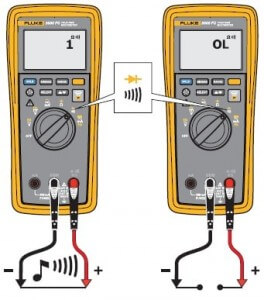
3000 FC Fluke wireless multimeter measurements
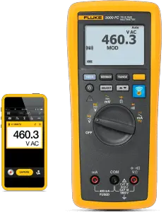
3000 FC series Fluke wireless Multimeter is used for measuring AC & DC voltages, Resistances,Capacitances, AC & DC current etc. In our last article we explain basic description of this multimeter, if you want to know its description you may follow this 3000FC fluke wireless multimeter.Well friends, this multimeter is based on the advanced technology will be very helpful for professional technicians because it measures hundreds of readings in a single click and you can share your results with your team members via Sharelive video calls.
How to measure AC & DC voltage with 3000 FC series Fluke wireless Multimeter?
Steps for AC & DC voltage measurement are:
- Firstly select the voltage ranges i.e. 600.0mV, 60.00V, 6.000V, 600.0V & 1000V.
- Set AC or DC voltage as per your requirement.
- Inside the com jack insert black lead.
- Inside the VΩ jack insert Red lead.
- Connect firstly the black lead to the circuit and after that the Red lead.
- Turn the switch to mṽ function.
- Press
 this button to toggle the product between the dc mill volts & ac mill volts.
 - Calculate the product can show the ratio of volts to the frequency of an ac signal.
- When the product is set to this ratio, then set voltage range manually.
- Now if the voltage exceeds its range, the product shows OL in the display otherwise the voltage drops, the value shown in the display can be the invalid.
- Note the measurement display on the screen. When you have noted the readings, first remove the red lead from the circuit and then remove the black lead to avoid any electrical shock or damage to the device.
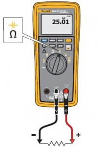
How to measure Resistance with 3000 FC series Fluke wireless Multimeter?
Steps for Resistance measurement are:
- Firstly select the resistance ranges i.e. 600.0 Ω, 60.00kΩ, 6.000kΩ, 600.0kΩ & 50.00MΩ.
- Set Resistance value as per your requirement.
- Inside the com jack insert black lead.
- Inside the VΩ jack insert Red lead.
- Connect firstly the black lead to the circuit and after that the Red lead.
- Turn the switch to Ω.
- For resistance measurement, the product sends the small current through the circuit between the probes.
- The resistance measured is the total resistance of all paths because the current flows through all possible paths between the probes.
- Note the measurement display on the screen. When you have noted the readings, first remove the red lead from the circuit and then remove the black lead to avoid any electrical shock or damage to the device.
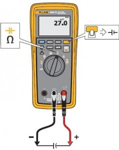
How to measure Capacitance with 3000 FC series Fluke wireless multimeter?
Steps for Capacitance measurement are:
- Firstly select the capacitance ranges i.e. 1,000 nF, 10.00 µF, 100.0 µF and 9999 µF.
- Set capacitance value as per your requirement.
- Inside the com jack insert black lead.
- Inside the VΩ jack insert Red lead.
- Connect firstly the black lead to the circuit and after that the Red lead.
- Turn the switch to

- Press
 this button to measure capacitance.
 - Note the measurement display on the screen. When you have noted the readings, first remove the red lead from the circuit and then remove the black lead to avoid any electrical shock or damage to the device.
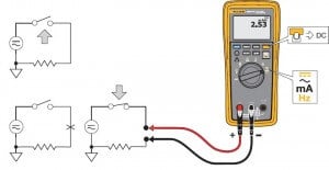
How to measure AC & DC current with 3000 FC series Fluke wireless multimeter?
Steps for measuring AC & DC current are:
- Firstly select the current ranges i.e. 60.00mA, 400 mA.
- Set AC or DC current as per your requirement.
- Inside the com jack insert black lead.
- Inside the mA jack insert Red lead.
- Connect firstly black lead to the circuit and after that Red lead.
- Press
 this button to toggle the product between the milli amp Ac & mill amp Dc.
 - Note the measurement display on the screen. When you have noted the readings, first remove the red lead from the circuit and then remove the black lead to avoid any electrical shock or damage to the device.
How to perform continuity test with 3000 FC series Fluke wireless multimeter?
Steps for continuity test are
- Turn the dial to
 .
. - Inside the com jack insert black lead.
- Inside the VΩ jack insert Red lead.
- Connect firstly the black lead to the circuit and after that the Red lead.
- The continuity uses a beeper that sounds when a closed circuit is sensed.
- The beeper lets you do the continuity test without the necessity to look at the display.
Hope this article will help you. For any suggestion please share with us.


