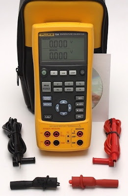
Measurements of Electrical Parameters
Measurements in Different Modes:
(A) Measure mode:
(i) Measuring Electrical parameters (Voltage and current) (Upper display)
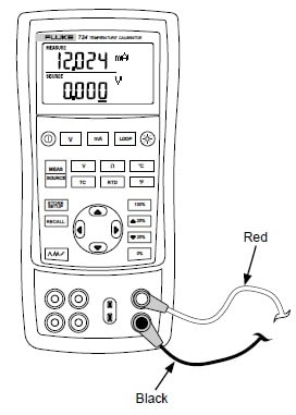
- Select current by pressing mA button.
- Ensures that loop button should not be “ON”.
- Inside the V/mA/loop jack, insert Red lead.
- Inside the COM jack, insert black lead.
- First connect black lead to the circuit and after that Red lead.
- Note the measurement display on the screen. When you have noted the readings, first remove the red lead from the circuit and then remove the black lead to avoid any electrical shock or damage to the device.
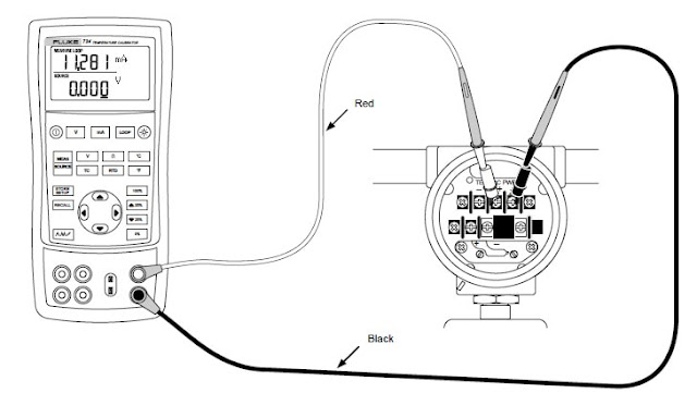
- Inside the V/mA/loop jack, insert Red lead.
- Inside the COM jack, insert black lead.
- First connect black lead to the circuit and after that Red lead.
- Connect the calibrator to the transmitter current loop terminal.
- When the calibrator is in the current measurement mode then press LOOP labelled button.
- LOOP start appearing which turns on the internal 24V loop supply.
- Note the measurement display on the screen. When you have noted the readings, first remove the red lead from the circuit and then remove the black lead to avoid any electrical shock or damage to the device.
(ii) Measuring Electrical Parameters (voltage and current) (Lower display)
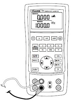
- Inside the V/Ω/RTD jack, insert Red lead.
- Inside the COM jack, insert black lead.
- First connect black lead to the circuit and after that Red lead.
- If necessary, press Meas/Source labelled button for measure mode (lower display).
- For dc voltage or current press V labelled button and for resistance press Ω labelled button.
- Note the measurement display on the screen. When you have noted the readings, first remove the red lead from the circuit and then remove the black lead to avoid any electrical shock or damage to the device.
How to measure Temperature with Fluke 724 temperature calibrator in measure mode?
Steps for measuring Temperature with Fluke 724 Temperature calibrator are:
(i) Measuring Temperature using Thermocouples:
Calibrator supports ten standard thermocouples including types E, N, J, K, T, B, R, S, L, or U. For the measurement following procedure follows:
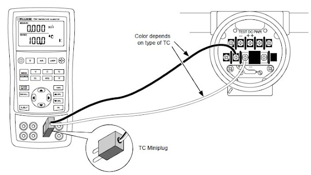
- Attach the thermocouple leads to the TC mini plug and insert mini plug into the TC input /output terminal of the calibrator.
- If necessary, press Meas/Source labelled button for measure mode.
- For TC display, press TC labelled button.
- For the selection of thermocouple type, press this TC labelled button continuously.
- For measuring temperature in Celsius or Fahrenheit, press °C or °F labelled button.
(ii) Measuring Temperature using RTD’s:
- If necessary, press Meas/Source labelled button for measure mode.
- For RTD display, press RTD labelled button.
- For the selection of RTD type, press this RTD labelled button continuously.
- Press
 button to select 2-, 3-, 4- wire connections.
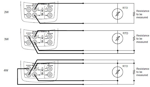
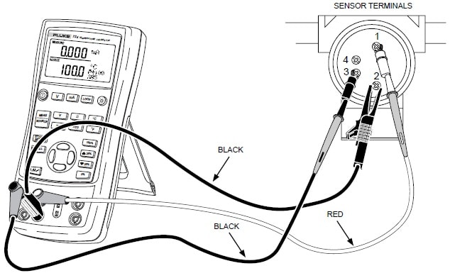
 - Attach RTD to the Input terminals as shown in set-up below.
- For measuring temperature in Celsius or Fahrenheit, press °C or °F labelled button.
(B) Source Mode:
In this mode, calibrator generates calibrated signals for testing and calibrating process instruments.
Steps for measuring Voltage or current with Fluke 724 Temperature calibrator in source mode are:
- Inside the V/Ω/RTD jack, insert Red lead.
- Inside the COM jack, insert black lead.
- First connect the black lead to the circuit and after that the Red lead.
- If necessary, press Meas/Source labelled button for measure mode.
- For dc voltage or current press V labelled button and for resistance press Ω labelled button.
- Enter the desired value by selectin
 button.
 - To select the different digit to change press
 button.
 - Note the measurement display on the screen. When you have noted the readings, first remove the red lead from the circuit and then remove the black lead to avoid any electrical shock or damage to the device.
How to measure Temperature with Fluke 724 temperature calibrator in source mode?
(i) Measuring Temperature using Simulating Thermocouples:
Calibrator supports ten standard thermocouples including types E, N, J, K, T, B, R, S, L, or U. For the measurement procedure is as follows:
- Attach the thermocouple leads to the TC mini plug and insert the mini plug into the TC input /output terminal of the calibrator.
- If necessary, press Meas/Source labelled button for measure mode.
- For TC display, press TC labelled button.
- For the selection of thermocouple type, press this TC labelled button continuously.
- Enter the temperature you want by pressing
 these buttons.
 - To select the different digit to edit press
 either of these buttons.
 - For measuring temperature in Celsius or Fahrenheit, press °C or °F labelled button.
(ii) Measuring Temperature using simulating RTD’s:
Calibrator accepts the RTD measurements inputs in 2-, 3-, 4- wire connections and prefers 3- wire connection the most. For measurement procedure is as follows:
- If necessary, press Meas/Source labelled button for measure mode.
- For RTD display press RTD labelled button.
- For the selection of RTD type, press this RTD labelled button continuously.
- Enter the temperature you want by pressing
 these buttons.
 - Select different digit, to edit press
 button.
 - Attach RTD to the Input terminals as shown in set-up below.
- When the excitation current from your device exceeds the limit of the 724 calibrator then it will display ExI HI.
It seems to be very interesting article hope this will help you. Have a look over it. We always appreciate your suggestion.


