The resistor is an electronic component that restricts or limits the flow of current and divides the voltage in an electronic circuit. It is one of the most important passive components of an electronics industry because, without these components, active devices cannot process the electrical signals. Its main purpose is to provide a precise quantity of electrical resistance. In our previous articles, we explain, capacitors, types of capacitors, diodes in detail. In this article, we are going to explain resistors, color coding, and types of resistors in detail.
Resistors Basics:
Resistors mainly added to those circuits where they complement the active components like integrated circuits, op-amp, microcontrollers etc. To form resistor networks it can be connected in various parallel and series combination.
-
Resistor Symbol
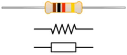
It is a two terminal device have one connection on each of its sides. Two common resistor symbols are shown in given figure; one is in American style (zig zag line) and other is international style. Resistor values displayed in ohms is critical for both evaluating and actually constructing the circuit. Each resistor in a circuit should have unique name/number. In a circuit diagram, the SI prefix symbol for a particular value in European countries is written as 2K4 which indicates a resistor value of 2.4KΩ etc.
-
Resistor working:
As per ohm’s law, the behaviour of an ideal resistor is explained by the given equation:
V= I * R
This law states that the ratio of the voltage and the current is equal to the constant i.e. resistance known as the constant of proportionality. For example, if a 200-ohm resistance is attached across the terminals of the 10V battery, then a current of 10/ 200 = 0.05 Ampere flows through that resistor. In alternating current circuits, practical resistors also have some inductance and capacitance. These are generally made up of metal wire or carbon and engineered to maintain a stable resistance value over a wide range of environmental conditions. In a working circuit, they do not produce light but they do produce heat as the electric power dissipated by them.
-
Resistor Color Code:
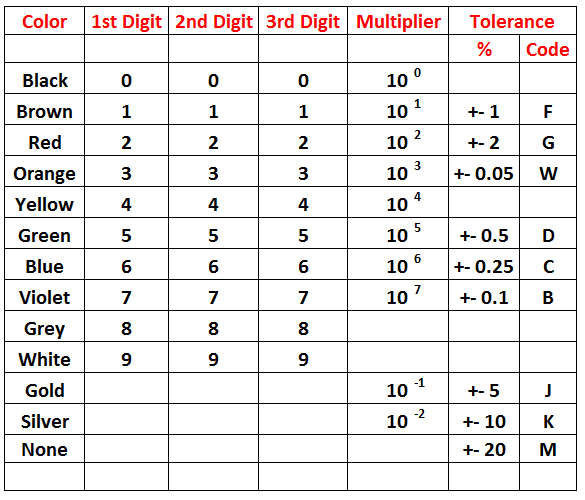
The system of representing the resistor value is known as colour coding. This coding is standardized by the Electronic Industries Association. The table given below shows the numerical value associated with each colour. To determine the value of resistance, colour bands are always read from left to right from the end that has the bands nearer to it.
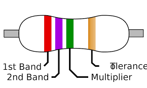
As shown in the diagram below, the first and second band represents the first and second significant digits of the resistance value. The third band is the multiplier represents the number of zeroes that follow the second digit. Sometimes, the third band is of golden or silver colour, then these colours represent a multiplying factor of 0.1 and 0.01 respectively. The fourth band represents the resistors tolerance i.e. the measure of the precision with which the resistor was made by the manufacturer. The silver band represents ±10 % and the gold represents the ±5 % tolerance.
Note: If there is no fourth band it shows that the resistor has ± 20% tolerance.
Resistor Types:
The two main characteristics of each resistor are resistance in ohms & power rating in watts. To obtain a desired current or voltage drop in the circuit, the value of Resistance is perfectly selected. The power rating may be as lower 1/10 Watt to as high as several hundred watts. From the operating point of view, resistors can be classified as fixed resistors and variable resistors.
-
Fixed Resistors:
Fixed resistors are those resistors that have a fixed value of resistance. These are two types:
(a) Carbon composition:
It is the most common resistor used in electronic circuits with a low power rating of 2W or less and is made of the mixture of carbon or graphite & clay. For insulation and mechanical strength, the resistor element is enclosed in a plastic case. This type of resistors is readily available in values ranging from 1 Ω to 22MΩ, having a tolerance range of 5 to 20% and power rating of 1/4, 1/2, 1 or 2W. When the wattage of the resistor increases, the relative size of resistors also got increased.
(b) Wire wound:
It is an electrical passive component that limits the current. For its construction, a resistance wire made of tungsten, nichrome or manganin etc are wrapped around a hollow porcelain cylindrical core. This whole assembly is coated with an enamel containing powdered glass. To provide mechanical protection to the device, hard and smooth coating is done. The power rating of this resistor is ranging from 2W to 500W and have values ranging from 1 Ω to 100 KΩ.
(ii) Variable Resistor:
In these type of resistors, the value of electrical resistance can be adjusted as per your requirement. To adjust the values of current and voltages these resistors are the best one. These are two types:
(a) Carbon composition:
In this resistor, a thin carbon coating on pressed paper or a moulded carbon disc constitutes the carbon composition resistance element. These are readily available in values ranging from 1000 Ω to 5 MΩ, approximately having a power rating of usually 1/2 to 2W. A carbon control is often combined with a power on-off switch.
(b) Wire wound:
In this type of resistor, a resistance wire is wound over a dough shaped the core of bakelite or ceramic. The two ends of the resistance wire are joined to the external soldering lug terminals.
Hope you all like this article. For any suggestions please comment below. We always appreciate your suggestions.


3 Comments